Milling mechanism of horizontal grinder
A mill and horizontal technology, which is applied in the field of grinding mechanism of horizontal mills, can solve problems affecting production efficiency and achieve the effects of improving production efficiency, reducing production space, and reducing noise
- Summary
- Abstract
- Description
- Claims
- Application Information
AI Technical Summary
Problems solved by technology
Method used
Image
Examples
Embodiment 1
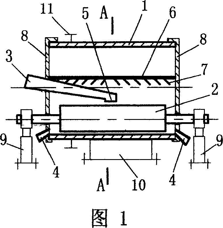
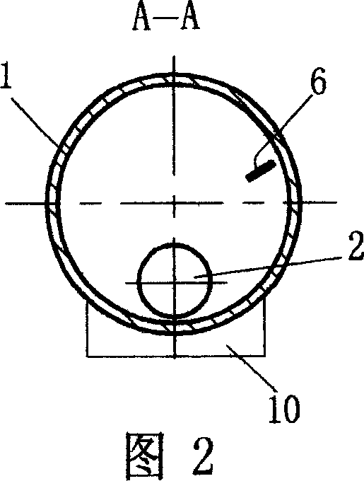
[0014] Example 1. See Figure 1 and Figure 2.
[0015] The grinding mechanism includes a grinding cylinder 1, a grinding roller 2 located in the grinding cylinder, and a feeding device 3. The roller surface of the grinding roller 2 and the inner wall surface of the grinding cylinder 1 form a grinding surface, and the feeding port 5 of the feeding device 3 Located in the middle of the grinding roller 2, the material enters the grinding surface from the middle of the grinding roller. The feeding device 3 can be a slide pipe, or other conveying devices such as a screw conveyor; During the milling process, the discharge ports 4 at both ends are simultaneously discharged. In addition, a bidirectional feeding device 6 is installed in the grinding cylinder 1 to make the material flow from the middle of the grinding roller to both ends. End flow member 7. The structure of the bidirectional feeding device can also be in other forms.
[0016] The main intention of the components repr...
Embodiment 2
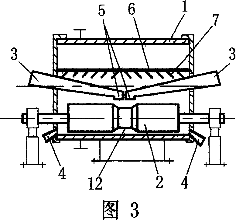
[0017] Example 2. See Figure 3.
[0018] This embodiment is improved on the basis of Embodiment 1, that is, a groove 12 is arranged in the middle of the grinding roller 2, and the feed port 5 of the feeding device 3 is located in the middle of the grinding roller 2, and the groove 12 is connected with the feeding device. Corresponding to the material inlet 5, the material entering from the material inlet 5 enters the grinding surface from the groove. This structure is convenient for material distribution and prevents the middle part of the grinding roller from being overstressed and vibrating due to material accumulation, which is conducive to improving the grinding effect. . Because the accumulation of materials in the middle part may cause the gap between the grinding roller's middle part to be too small and the two ends to be too large, the gap between the two ends is too large to affect the grinding effect, so this structure is beneficial to improve the grinding effect. ...
Embodiment 3
[0022] Example 3. See Figure 4, Figure 5.
[0023] In this example, two grinding rollers 2 are arranged in the grinding cylinder 1, which are symmetrically arranged up and down in this example. Setting two grinding rollers can form two running-in surfaces with the inner wall surface of the grinding cylinder 1, which is beneficial to improving production efficiency and processing of fine powder. Other corresponding embodiments with the aforementioned.
PUM
 Abstract
Description
Claims
Application Information
 - R&D
- Intellectual Property
- Life Sciences
- Materials
- Tech Scout
- Unparalleled Data Quality
- Higher Quality Content
- 60% Fewer Hallucinations
Browse by: Latest US Patents, China's latest patents, Technical Efficacy Thesaurus, Application Domain, Technology Topic, Popular Technical Reports.
© 2025 PatSnap. All rights reserved.Legal|Privacy policy|Modern Slavery Act Transparency Statement|Sitemap|About US| Contact US: help@patsnap.com


