Connector

A connector and pipe connection technology, applied in the direction of couplings, mechanical equipment, etc., can solve the problems of high cost, troublesome forming, easy to fall off, etc., and achieve the effect of improving rigidity, superior assembly operability, and preventing friction loss or deformation.

Inactive Publication Date: 2007-04-25
TOYODA GOSEI CO LTD
View PDF4 Cites 0 Cited by
  • Summary
  • Abstract
  • Description
  • Claims
  • Application Information

AI Technical Summary

Problems solved by technology

[0003] However, since the engaging claw 112 has a shape protruding from the peripheral portion of the opening of the tube-shaped holder 110, there is a problem that it is easy to fall off when a torque or impact is applied between the tube P and the tube T.
In addition, the shape of the retainer 110 has a complex structure and is troublesome to form, which is a major cause of high cost.

Method used


Image

  • Connector
  • Connector
  • Connector

Examples


Embodiment Construction

[0036] In order to further clarify the structure and operation of the present invention described above, preferred embodiments of the present invention will be described below.

[0037] (1) Outline of the structure of the connector 10

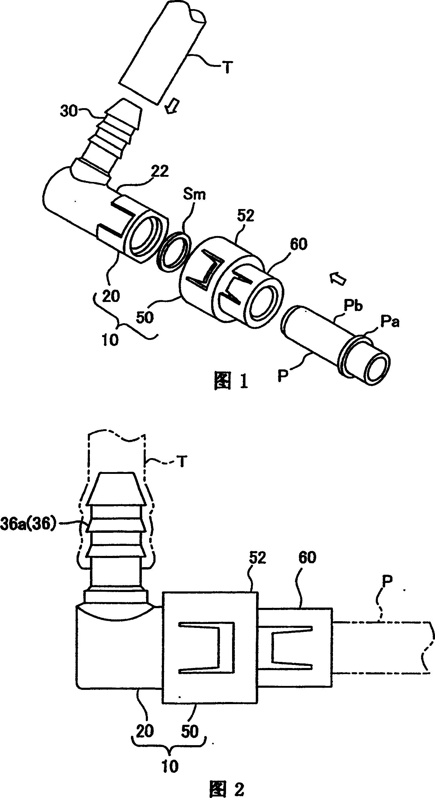
[0038] The connector according to the present invention can be suitably arranged, for example, on a fuel passage of a fuel tank of an automobile. 1 is a perspective view illustrating a connection structure before connecting a pipe P and a hose T to a connector 10 according to an embodiment of the present invention, and FIG. 2 is a side view of the connector 10 . In FIGS. 1 and 2 , the connector 10 includes a connector body 20 , a retainer 50 assembled to the connector body 20 , and a seal member Sm inserted into the connector body 20 to seal the pipe P. As shown in FIG. The pipe P has a flange Pa protruding from its outer peripheral portion, and the outer peripheral surface on the front end side of the flange Pa serves as a sealing surface Pb,...


PUM


Abstract

This invention provides a connector 10 of simple constitution free of the risk to slip off easily with an external force. The connector 10 comprises a connector body 20 and a retainer 50. The connector body 20 is composed of a pipe connection part 22 having a pipe inserting hole 26 and a connector side mounting mechanism for mounting the retainer 50, while the retainer 50 has a retainer side mounting mechanism for mounting on the connector body 20. The connector side mounting mechanism has a non-circular fitting part 24 in which the outside shape of the pipe connection part 22 is formed from a circular arc portion 24a and a straight portion 24b and a connector side engagement part 28. The retainer side mounting mechanism has a coupling hole 54 to be fitted in the non-circular fitting part 24 and a retainer side engagement part 56 to be engaged with the connector side engagement part 28 when the retainer 50 is inserted axially into the connector body 20 with the coupling hole 54 positioned mating with the non-circular fitting part.

Description

technical field [0001] The present invention relates to a connector in which a tube is connected to a connector body through a retainer. Background technique [0002] The technique of Patent Document 1 is known as a conventional connector of this type. Fig. 14 is a sectional view showing a conventional connector. In FIG. 14 , the connector 100 connects the hose T and the pipe P, and includes a connector body 102 for connecting the hose T and a holder 110 for holding the pipe P. The connector body 102 is assembled with the holder 110 to form a . The holder 110 has a cylindrical shape, and an engaging claw 112 is formed on its front end, and the engaging claw 112 is assembled by engaging with the shoulder 104 of the connector main body 102 . [0003] However, since the engaging claw 112 has a shape protruding from the opening peripheral portion of the tube-shaped holder 110 , there is a problem that it is easy to fall off when a torque or impact is applied between the pipe ...

Claims


Application Information

Patent Timeline
Patent Type & Authority Patents(China)
IPC IPC(8): F16L37/12
Inventor 竹内雪治青木智英
Owner TOYODA GOSEI CO LTD
Why Eureka
Try Eureka