
Down-hole cored tubular substance

A technique for tubular objects and tubular walls, applied in the field of devices for receiving insertion tools

Inactive Publication Date: 2007-04-25
SCHLUMBERGER OVERSEAS SA
View PDF25 Cites 2 Cited by
  • Summary
  • Abstract
  • Description
  • Claims
  • Application Information

AI Technical Summary

Problems solved by technology

But none of these proposed systems relate to measurement or signal transmission through the tube

Method used


Image

  • Down-hole cored tubular substance
  • Down-hole cored tubular substance
  • Down-hole cored tubular substance

Examples


Embodiment Construction

[0049] In the interest of clarity, not all parts of an actual appliance are described in this specification. It will be appreciated that those of ordinary skill in the art would nonetheless be engaged in their day-to-day work with the benefit of this disclosure, although the development of any such practical appliance might be complex and time-consuming.

[0050] The apparatus of the present invention includes two main pieces of equipment, an insertion tool (RIT) and a drill collar. In the future, the drill collar will be called sub-tube.

[0051] Insertion Tool (RIT)

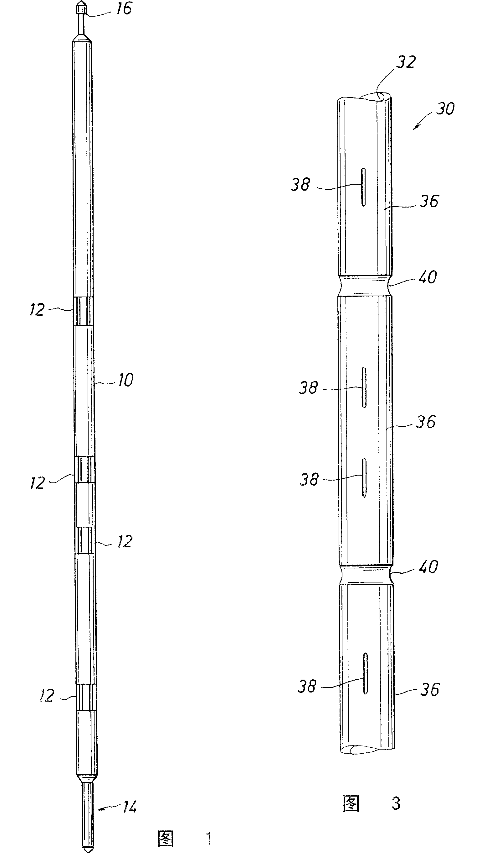
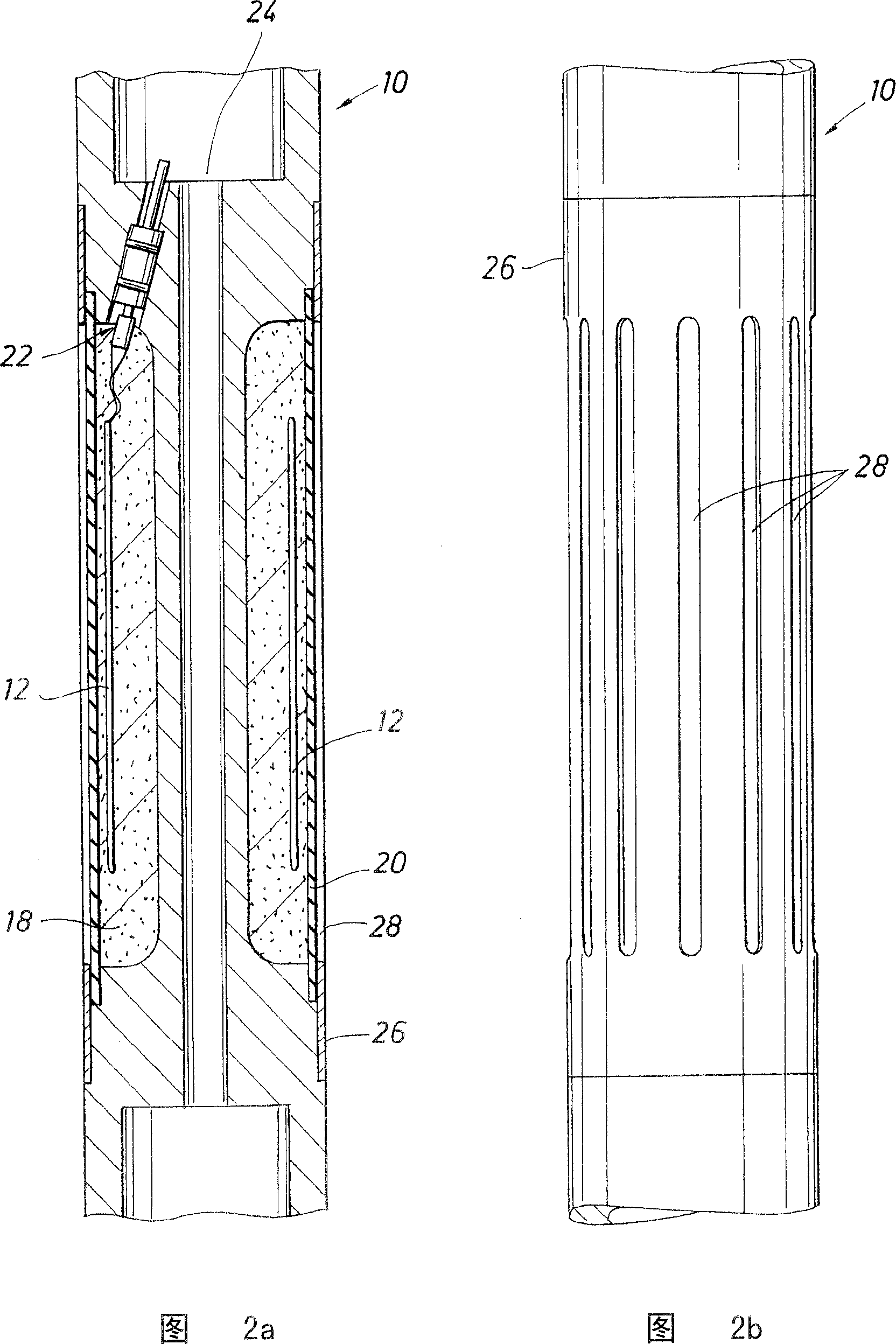
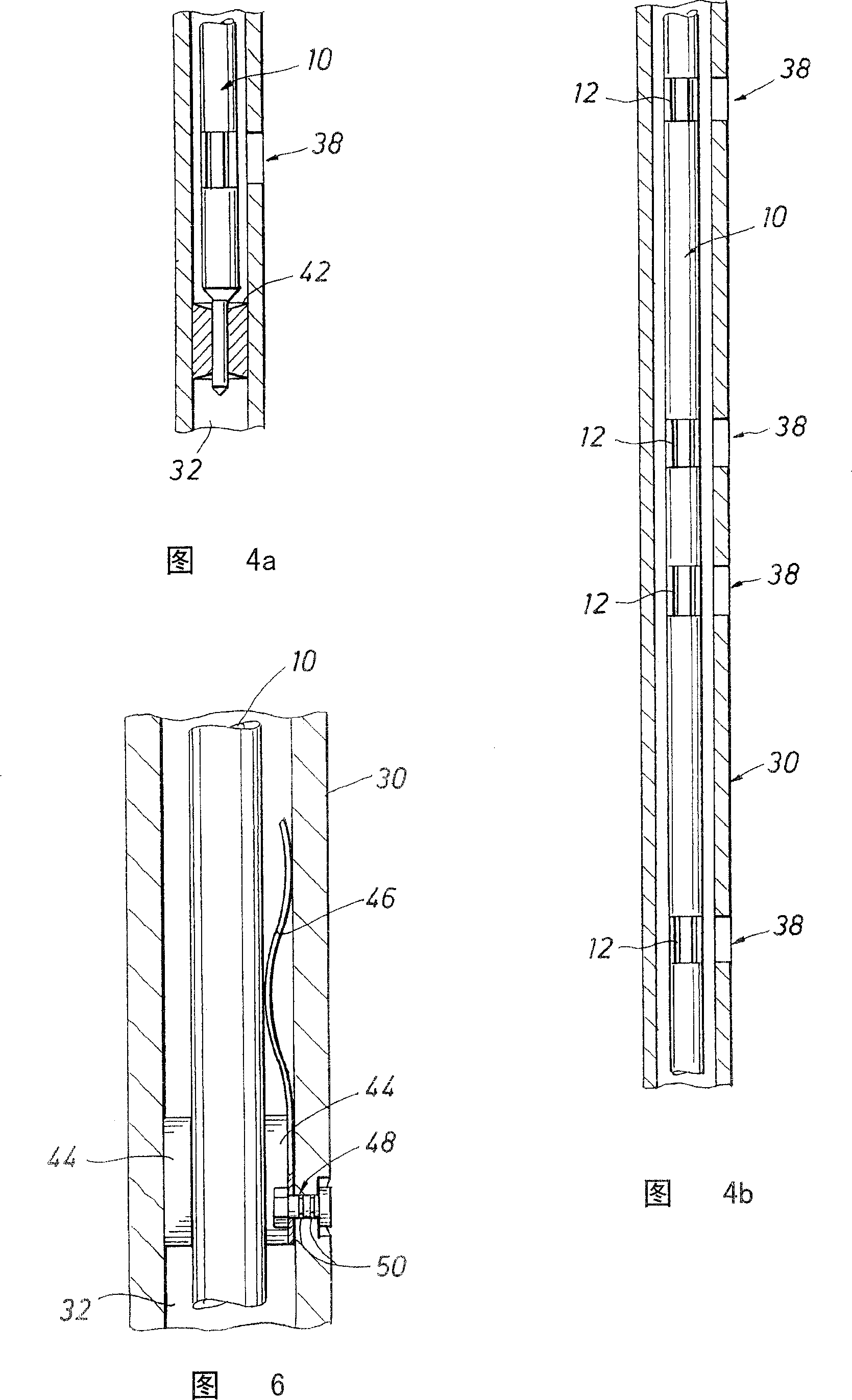
[0052] Figure 1 shows one embodiment of a RIT 10 of the present invention. The RIT 10 is an elongated, small diameter metal mandrel that can house one or more antennas 12, signal sources, sensors (sensor / detector are interchangeable terms as used herein), magnets, gamma ray probes, Generator / generator device, neutron generation / detection device, various electronic instruments, battery, downhole information p...


PUM


Abstract

A system and method for underground communication and measurement by an improved tubular metal device. The device has a slender body with a tube wall and a central hole for holding inserted tool. Some slots on the tubular device are used for signal transmitting and / or receiving. Sensors and / or signalers are mounted in the inserted tool which is passed by drilling set so as to attach to the tubular device. The inserted tool contains a modem for wireless communication with ground and / or far end of underground in real time and a reductive coupler for radio signal transmission.

Description

technical field [0001] The present invention relates generally to surveying subterranean formations, systems and methods for transmitting and / or receiving signals through metal tubulars, and more particularly to devices for receiving insertion tools. Background technique [0002] Resistivity and gamma ray recordings are two of the most commonly used formation evaluation measurements in well logging. Such measurements are commonly used to determine and evaluate the properties of potential hydrocarbon-bearing zones in subterranean formations. In many wells, they are the only two survey measurements, especially in low cost wells and the surface and intermediate sections of more expensive wells. [0003] These logging techniques are implemented in different ways. Well logging tools include a number of transmitting and detecting devices for measuring various parameters, which can be lowered into the well at the end of a cable or wireline. The cable is connected on the surface ...

Claims


Application Information

Patent Timeline
Patent Type & Authority Patents(China)
IPC IPC(8): G01V3/18G01V3/34E21B47/12
Inventor B·克拉克J·亨卡M·T·弗雷D·L·史密斯D·拉马斯瓦米A·L·科林斯S·D·邦纳
Owner SCHLUMBERGER OVERSEAS SA
Learn More