
Shock-absorbing mechanism of motor bearing

A bearing and motor technology, applied in the field of anti-vibration mechanism of shaking or vibration, can solve the problems of increasing vibration and abnormal sound, shaking of the shaft 14, generating vibration, etc., to achieve the effect of increasing the life of the fan

Inactive Publication Date: 2007-05-09
ASIA VITAL COMPONENTS SHENZHEN CO LTD
View PDF4 Cites 0 Cited by
  • Summary
  • Abstract
  • Description
  • Claims
  • Application Information

AI Technical Summary

Problems solved by technology

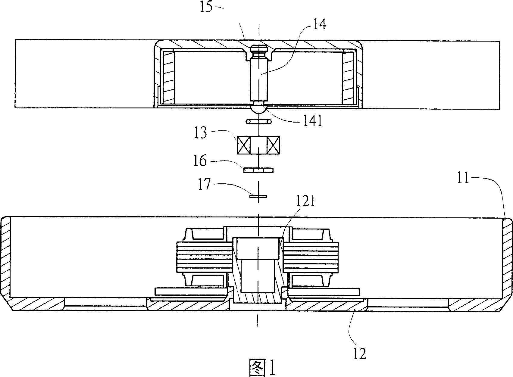
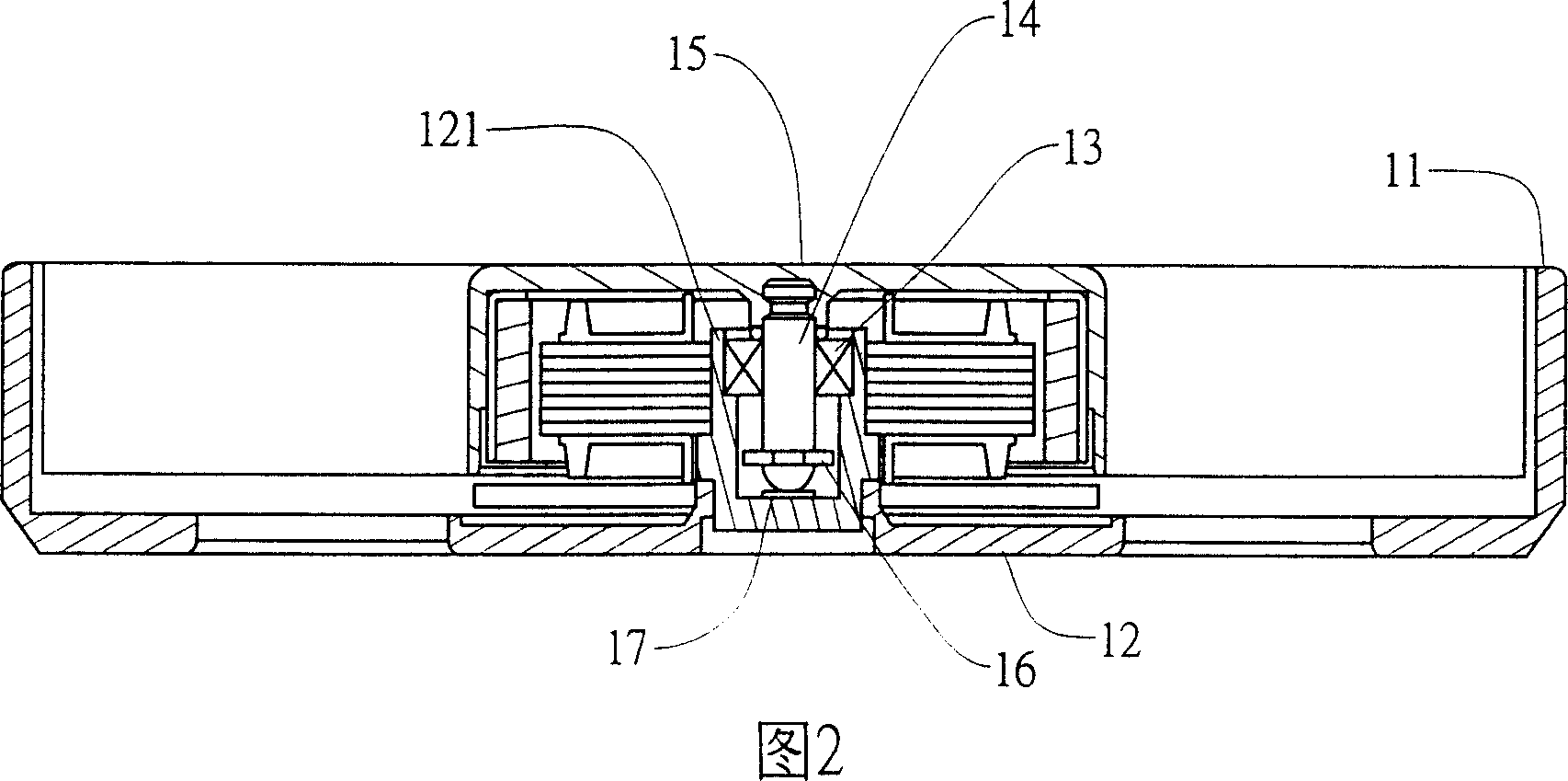
[0002] Please refer to the traditional motor axis support structure shown in Fig. 1 and Fig. 2. As shown in the figure, it at least includes a fan frame 11, and at least one support seat 12 is formed in the fan frame 11, and a support seat 12 is formed on the support seat 12. Hollow shaft tube 121, at least one bearing 13 and one shaft center 14 are arranged in the shaft tube 121, one end of the shaft center 14 passes through the bearing 13 to be pivoted on the support seat 12, and the other end of the shaft center 14 is connected to a fan wheel 15 , and the shaft 14 has a neck 141 through one end of the bearing 13, so that a buckle 16 is fastened, and the bearing 13 is interfered by the buckle 16 to prevent the shaft 14 from running At the time, it will come out from the shaft tube 121, and the bottom of the shaft tube 121 is provided with a wear-resistant pad 17 to make one end of the shaft center 14 touch, and reduce the friction force when the shaft center 14 is running; When the shaft 14 rotates in the bearing 13, the internal clearance of the bearing 13 will cause the shaft 14 to shake; and when the shaft 14 rotates, it will be affected by external disturbances such as: airflow resistance and the weight of the shaft. , and the shaft 14 will also vibrate at different rotation speeds, which will greatly increase the disadvantages of vibration and abnormal noise generated during operation

Method used


Image

  • Shock-absorbing mechanism of motor bearing
  • Shock-absorbing mechanism of motor bearing
  • Shock-absorbing mechanism of motor bearing

Examples


Embodiment Construction

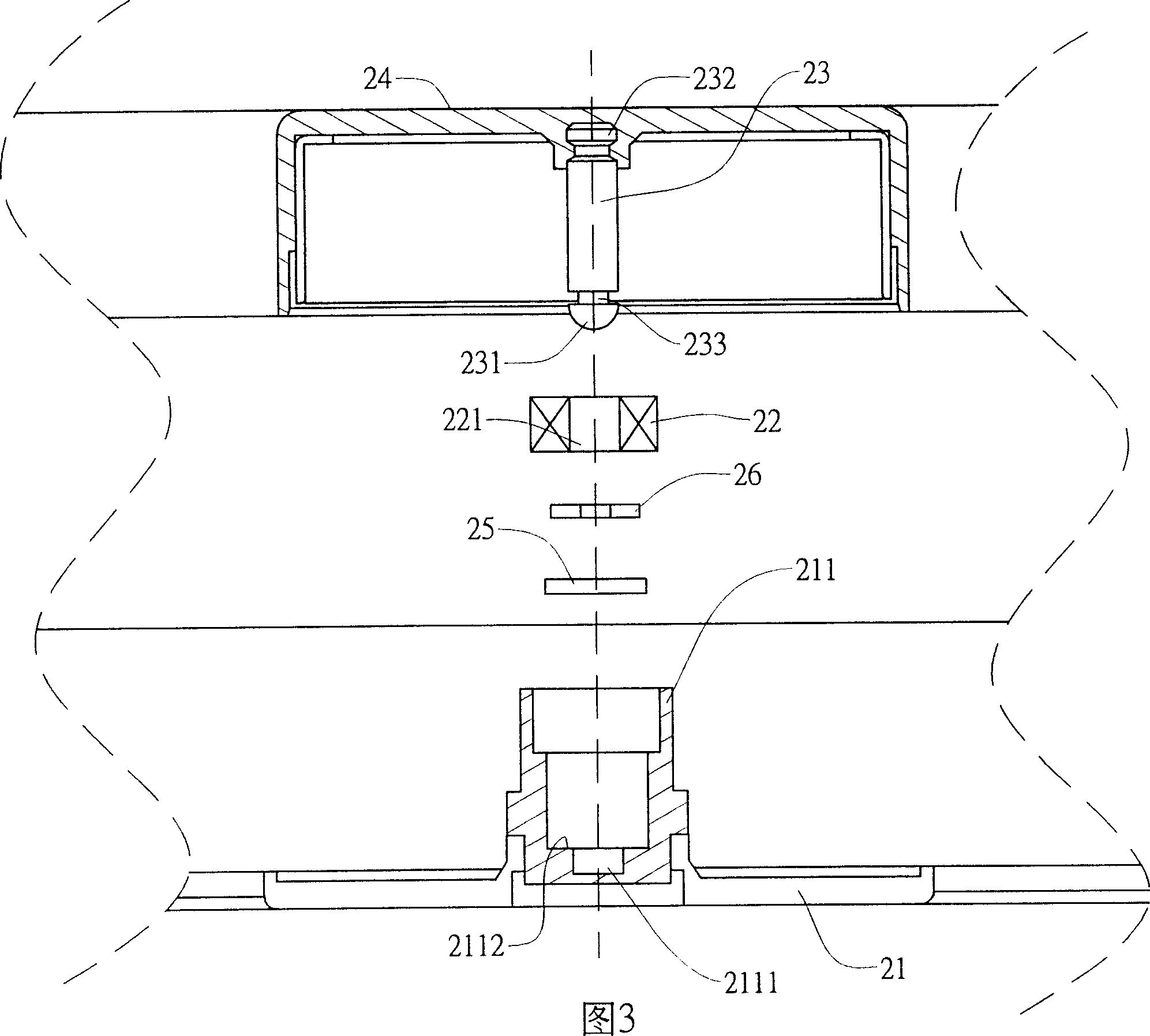
[0022] The present invention is a shockproof mechanism for motor bearings. Please refer to the first preferred embodiment of the present invention shown in FIGS. 3 to 5. As shown in FIGS. , a hollow shaft cylinder 211 is formed on it, a groove 2111 is formed at the inner bottom of the shaft cylinder 211, the groove 2111 has a convex portion 2112, and at least one shock absorbing component 25 is arranged on the convex portion 2112, and a A bearing 22 having a through hole 221 is arranged in the shaft cylinder 211, and a shaft 23, one end 232 of the shaft 23 is connected to a fan wheel 24, and the other end 231 of the shaft 23 has a neck 233 and runs through the shaft. The through hole 221 of the bearing 22 is fastened to the neck 233 through a snap ring 26, so that the shaft center 23 is pivotally arranged in the shaft tube 211, preventing the shaft center 231 from falling off from the shaft tube 221, and making the shaft center 23 The other end 231 of the shaft contacts the sh...


PUM


Abstract

The invention at least consists of a hollow beam barrel, an axle center and a damping component. A flute is set at bottom in axle barrel, and the flute has a convex. A bearing with through hole is set in beam barrel. The damping component is set on the convex in flute, and between the damping component and the flute a buffer space is formed. The axle center is pin joint in beam barrel, and touches the damping component. When axle center rotates, by support of damping component, the damping component reduces the shock generated from rotation.

Description

technical field [0001] The invention relates to an anti-vibration mechanism of a motor bearing, in particular to an anti-vibration mechanism for reducing shaking or vibration generated when the motor is running. Background technique [0002] Please refer to the traditional motor axis support structure shown in Fig. 1 and Fig. 2. As shown in the figure, it at least includes a fan frame 11, and at least one support seat 12 is formed in the fan frame 11, and a support seat 12 is formed on the support seat 12. Hollow shaft tube 121, at least one bearing 13 and one shaft center 14 are arranged in the shaft tube 121, one end of the shaft center 14 passes through the bearing 13 to be pivoted on the support seat 12, and the other end of the shaft center 14 is connected to a fan wheel 15 , and the shaft 14 has a neck 141 through one end of the bearing 13, so that a buckle 16 is fastened, and the bearing 13 is interfered by the buckle 16 to prevent the shaft 14 from running At the ti...

Claims


Application Information

Patent Timeline
IPC IPC(8): H02K5/24
Inventor 刘文豪洪尔泰
Owner ASIA VITAL COMPONENTS SHENZHEN CO LTD
Learn More