
UV-LED light source

A UV-LED and light source technology, applied in the field of inkjet printing, can solve problems such as failure of the air cooling mechanism, damage to the lamp head, and the inability of the fan to rotate, so as to prolong the life of the fan, ensure uniformity, and improve heat dissipation efficiency.

Active Publication Date: 2019-08-16
武汉优炜芯科技有限公司
View PDF5 Cites 1 Cited by
  • Summary
  • Abstract
  • Description
  • Claims
  • Application Information

AI Technical Summary

Problems solved by technology

The ink accumulated on the surface of the fan will cause the fan to fail to rotate, which will cause the air cooling mechanism to fail, and eventually the lamp head will be overheated and damaged
The ink accumulated on the surface of the heat sink will reduce the heat dissipation efficiency of the heat sink, and will also cause the temperature of the lamp head to rise, which will affect the reliability of the lamp head

Method used


Image

  • UV-LED light source
  • UV-LED light source
  • UV-LED light source

Examples


Embodiment Construction

[0016] The following will clearly and completely describe the technical solutions in the embodiments of the present invention with reference to the accompanying drawings in the embodiments of the present invention. Obviously, the described embodiments are only some, not all, embodiments of the present invention. Based on the embodiments of the present invention, all other embodiments obtained by persons of ordinary skill in the art without making creative efforts belong to the protection scope of the present invention.

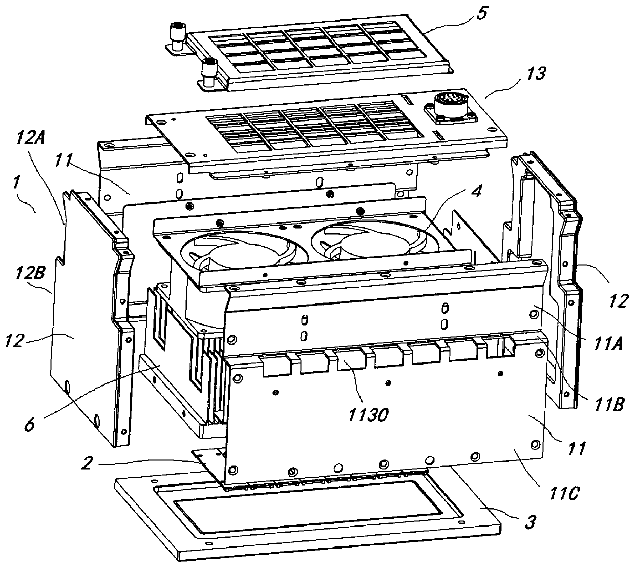
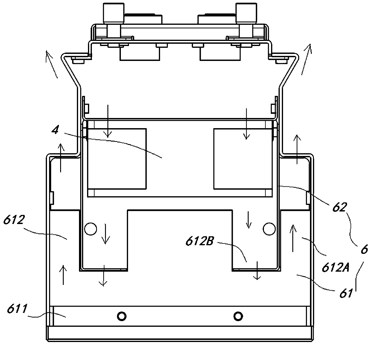
[0017] see figure 1 The UV-LED light source has a housing 1, the housing 1 includes a pair of first side plates 11 in the length direction, a pair of second side plates 12 in the width direction and a bottom plate 13, and a plurality of opposite bottom plates are formed on the first side plate 11 The air outlet hole 1130 in the direction of 13 is open on the end surface of the casing 1 opposite to the bottom plate 13 , and the inside of the casing 1 forms a ca...


PUM


Abstract

The invention discloses an UV-LED light source. The UV-LED light source comprises a shell body, a COB module, a top cover module, a plurality of fans, a filter module and an air channel module, wherein the shell body comprises a pair of first side plates, a second side plate and a bottom plate, air outlet holes are formed in the first side plates, and an accommodating cavity is formed in the shellbody; the filter module is arranged between the fans and the bottom plate, and used for filtering air entering from the bottom plate; and the air channel module is arranged between the fans and the COB module, and guides out air which is guided in by the fans and forms a pair of air curtains which extend along the surfaces of the first side plates. The UV-LED light source has the following beneficial effects: ink and dust which are sucked in by the UV-LED light source and diffuse in air during air inlet can be reduced, so that the lives of the fans are prolonged; and air flow in the air channel uniformly passes through heat dissipation fins, so that the heat dissipation efficiency is increased. After air enters the air channel module, due to the blocking of L-shaped baffles at the two sides of each fan, air is uniformly distributed into the fins, so that the uniformity of heat dissipation is ensured, and the heat dissipation efficiency is increased.

Description

technical field [0001] The invention relates to the field of spray painting, in particular to a UV-LED light source. Background technique [0002] In recent years, the UV-LED market and applications have shown a trend of rapid development. Compared with mercury lamps, UV-LED has the advantages of lower energy consumption, longer life and non-toxic environmental protection. With the help of Minamata Convention and preferential policies such as power saving, UV-LED's replacement of mercury lamps continues to increase, and its applications are becoming more and more diverse. change. At present, the photocuring market accounts for 80% of the market share of UV-LED applications, including inkjet printing, printing, exposure, coating and other application fields. [0003] UV lamps for printing urgently need air-cooled UV-LED light sources with compact structure and high integration. However, the promotion of air-cooled UV-LED light sources on the market in this application fiel...

Claims


Application Information

Patent Timeline
IPC IPC(8): B05D3/06F21V29/83F21V29/76F21V29/67
CPCB05D3/067F21V29/83F21V29/76F21V29/67
Inventor 郭峰胡聪韩杰张建宝
Owner 武汉优炜芯科技有限公司
Learn More