Hair transplanter

A hair transplant and hair technology, applied in skin transplantation, medical science, surgery, etc., can solve the problems of low fixation rate, poor scalp insertion, scalp injury and bleeding, etc., and achieve the effect of improving efficiency

Inactive Publication Date: 2001-10-24
金政澈
View PDF0 Cites 9 Cited by
  • Summary
  • Abstract
  • Description
  • Claims
  • Application Information

AI Technical Summary

Problems solved by technology

As a result, the hair root is fixed in the scalp after a prolonged period of time, so its fixation rate is low
[0005] In addition, in the conventional hair transplanter 10, the tip of the needle 1 has a predetermined angle, so the insertion into the scalp is not smooth, so that the scalp is often damaged and bleeds.

Method used


Image

  • Hair transplanter
  • Hair transplanter
  • Hair transplanter

Examples


Embodiment Construction

[0020] Detailed Description of Preferred Embodiments

[0021] A hair transplanter according to a preferred embodiment of the present invention will now be described in detail with reference to the accompanying drawings.

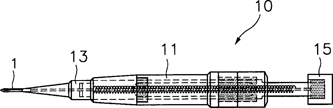
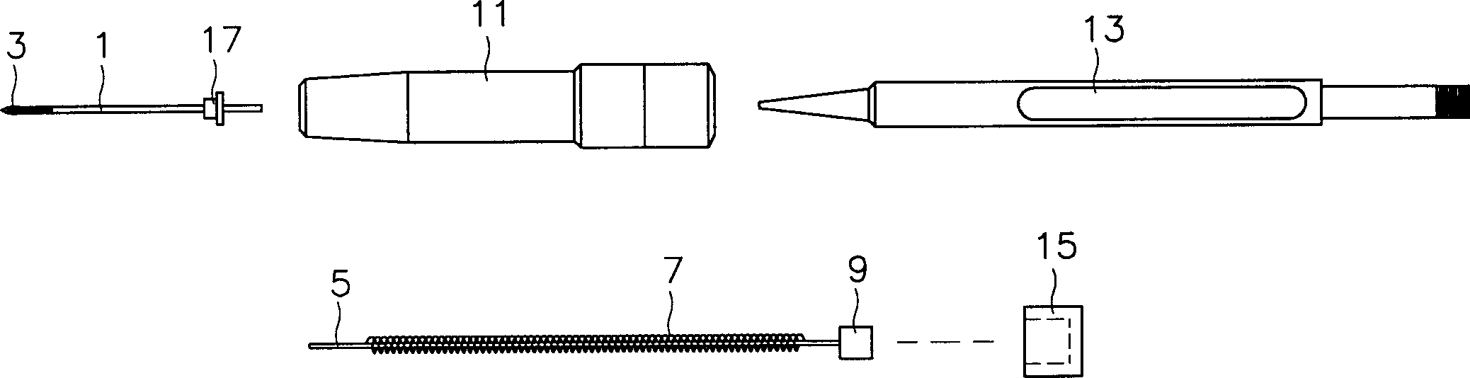
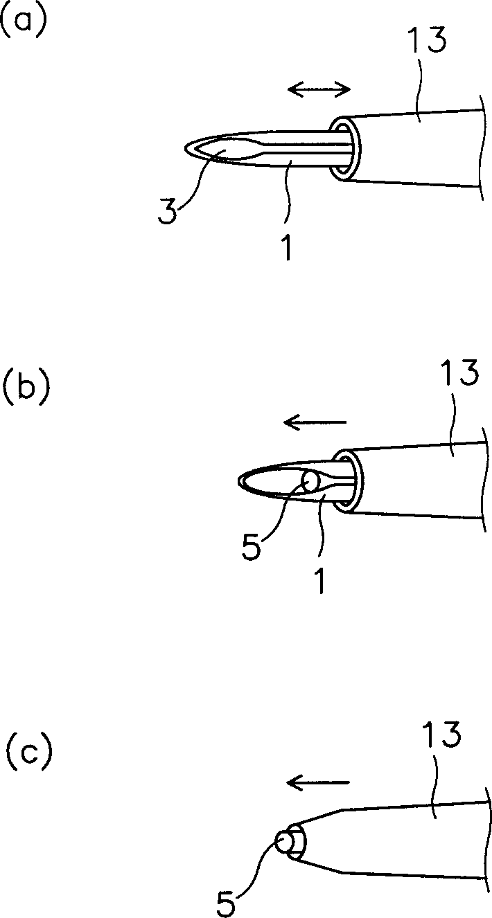
[0022] Fig. 2a is the perspective view of the hair transplanter of the first embodiment of the present invention; Fig. 2b is the perspective view of the exploded state of the hair transplanter shown in Fig. 2a; Fig. 2c is the working state of the hair transplanter shown in Fig. 2a picture. As shown in the figure, the hair transplanter 30 comprises: a needle head 21, which has a hair root at its end; a hand-held device 25, which is provided with a needle head 21 on its front middle part, and has a cavity of predetermined size inside it; Part 23 is inserted into the hand-held device 25, and is reciprocated by an external force for a predetermined distance in its longitudinal direction. The needle 21 in the hand-held device 25 passes through the inner center of...


PUM


Abstract

The present invention discloses a hair transplanter. A needle to be inserted into a scalp has a pointed end portion to reduce damage of the scalp, and a guide plate is adhered to an end portion of a sliding unit reciprocating in the longitudinal direction of the needle outside the needle, in order to prevent hair roots from being separated at the time of the separation of the needle. As a result, the hair roots inserted into a needle insertion groove are not damaged and are naturally settled in the scalp, thereby stably performing the hair transplantation.

Description

Background of the invention [0001] The present invention relates to a hair transplanter, in particular to an improved hair transplanter, which can stably implant the hair root inserted into its needle into a predetermined position on the scalp during the hair transplantation process without causing Deformed or damaged hair roots. [0002] Figures 1a and 1b show a conventional hair transplanter. Figure 1a is a schematic diagram of the assembled hair transplantation device. Figure 1b is an exploded view of the hair transplanter of Figure 1a. Fig. 1c shows the working state of the hair transplanter for transplanting hair roots. [0003] As shown in the figure, a conventional hair transplanter 10 includes: a needle 1, which has an end portion inserted into a predetermined position of the scalp with a hair root; a hand-held device 11, wherein the needle 1 is set; a slide inserted into the hand-held device 11; A member 13 moves a predetermined distance in the longitudinal direct...

Claims


Application Information

Patent Timeline
Patent Type & Authority Applications(China)
IPC IPC(8): A61B17/00A61B17/34A61F2/10
CPCA61F2/10A61B17/3468A61B2017/00752A61B17/00
Inventor 金政澈
Owner 金政澈
Why Eureka
Try Eureka