Switch device

A technology of switching devices and fixed contacts, which is applied in the direction of electric switches, electrical components, circuits, etc., to achieve the effects of improving durability, stable contact, and seeking long life

Active Publication Date: 2007-07-04
ALPS ALPINE CO LTD
View PDF3 Cites 0 Cited by
  • Summary
  • Abstract
  • Description
  • Claims
  • Application Information

AI Technical Summary

Problems solved by technology

[0011] Therefore, it is necessary to use a dedicated switchgear according to each application, and it is necessary to review the switchgear used in the product update of the car, and when there is a change from a high-load area to a small area, it has to be compared. big change problem

Method used


Image

  • Switch device
  • Switch device
  • Switch device

Examples


Embodiment Construction

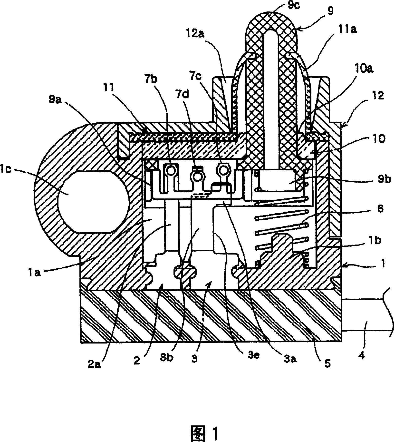
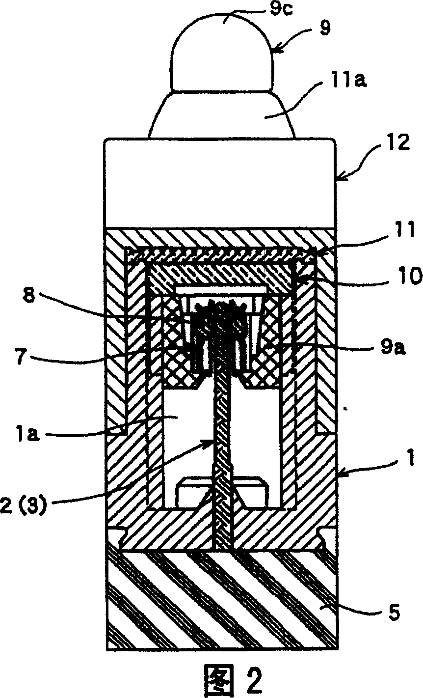
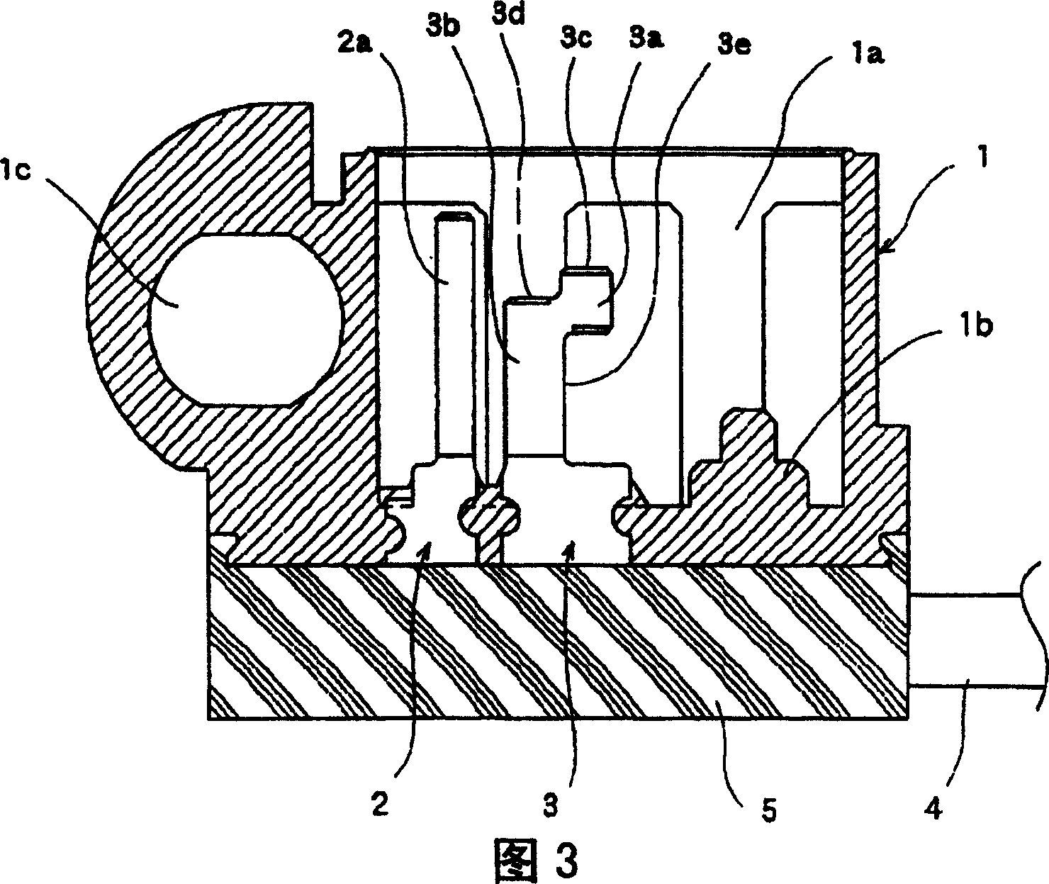
[0034] Hereinafter, an embodiment of the switch device according to the present invention will be shown with reference to FIGS. 1 to 8 . 1 is a sectional view showing a switchgear of the present invention, FIG. 2 is a sectional view of main parts viewed from different directions of the switchgear, FIG. 3 is a sectional view of a housing, FIG. 4 is a top view of a movable contact, and FIG. 5 is a movable contact. 6 is a cross-sectional view showing a state in which the contact part for arc consumption is connected, and FIG. 7 is a cross-sectional view showing a state in which the contact part for switching is connected. Cutaway view of the open state.

[0035] In FIGS. 1 to 3 , the case 1 is made of an insulating material such as synthetic resin, and is formed in a box shape with an open top surface having a storage portion 1 a inside. On the inner bottom surface of the accommodating portion 1 a of the case 1 , a flat plate-shaped common fixed contact 2 and an individual fixed...


PUM


Abstract

The invention provides a switch device capable of corresponding to a high load area and a minute area, resistant against the consumption due to the arc at a high load, capable of obtaining stable contact. A first contact part 7b contacting a common fixed contact 2, and second and third contact parts 7c, 7d contacting an individual fixed contact 3 are formed at a movable contact 7, and a first contact part 3c for arc consumption contacting the second contact part 7c along the direction perpendicular to the elevation direction of a driving member 9 earlier, and a second contact part 3d contacting the third contact part 7d later are formed on the individual fixed contact 3. The lower surface side of the second contact part 3d is applied as a contact surface contacting the third contact part 7d, and a non-conductive part separating from the second contact part 7c is formed on a contacting trace of the second contacting part 7c.

Description

technical field [0001] The present invention relates to a vehicle-mounted switch device, and more particularly to a structure using a switch device for lighting when a door of an automobile is opened and closed. Background technique [0002] As the structure of the conventional switchgear, since it is necessary to switch the lamp load, a microswitch-type detection switch that can be used in a high-load area is used (for example, refer to Patent Document 1). [0003] Hereinafter, the configuration of a conventional microswitch type switch device for vehicles will be described with reference to the drawings. FIG. 9 is a cross-sectional view showing the structure of a conventional microswitch-type switch device. [0004] In FIG. 9 , the switch device comprises a case 51 with a base 52 and a cover 53 . Contacts 56 , 57 , 58 are inserted into the base 52 , and one end thereof protrudes outward to form connection contacts 60 , 61 , 62 . In addition, the contacts 57 and 58 are a...

Claims


Application Information

Patent Timeline
Patent Type & Authority Patents(China)
IPC IPC(8): H01H13/18H01H13/20H01H13/02H01H13/14H01H13/52
Inventor 武田昌之
Owner ALPS ALPINE CO LTD
Why Eureka
Try Eureka