Switch device

A technology of switching devices and fixed contacts, applied in the direction of electric switches, electrical components, circuits, etc., to achieve stable contact, improve durability, and prevent cutting effects

Active Publication Date: 2005-06-01
ALPS ALPINE CO LTD
View PDF1 Cites 0 Cited by
  • Summary
  • Abstract
  • Description
  • Claims
  • Application Information

AI Technical Summary

Problems solved by technology

[0011] Therefore, it is necessary to use a dedicated switchgear according to each application, and it is necessary to review the switchgear used in the product update of the car, and when there is a change from a high-load area to a small area, it has to be compared. big change problem

Method used


Image

  • Switch device
  • Switch device
  • Switch device

Examples


Embodiment Construction

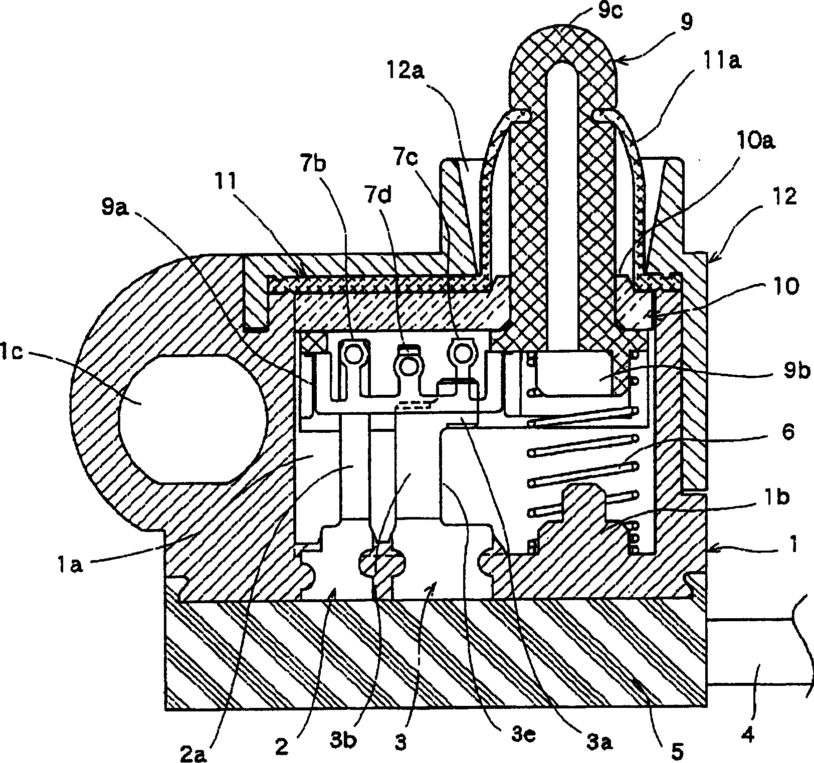
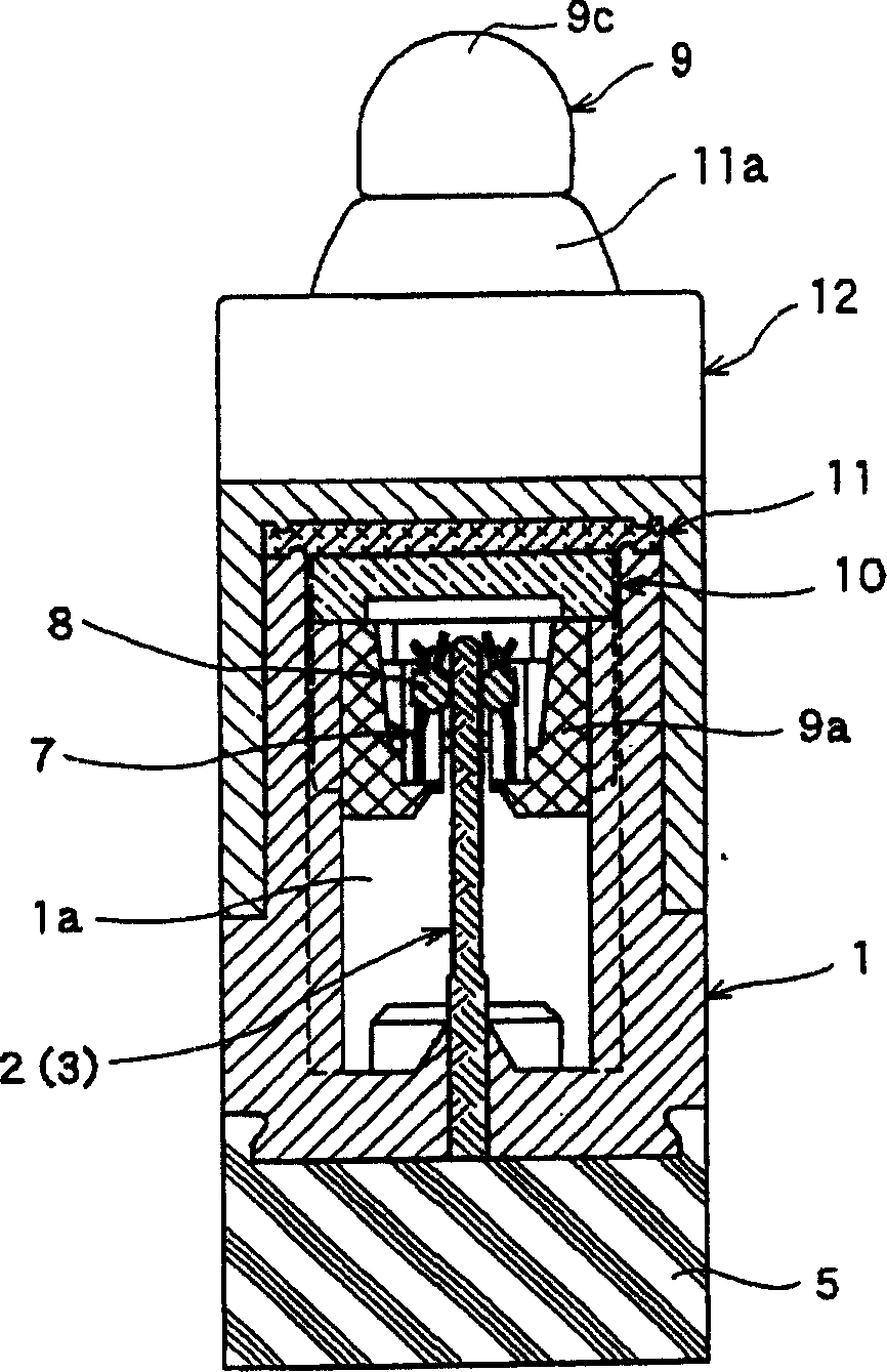
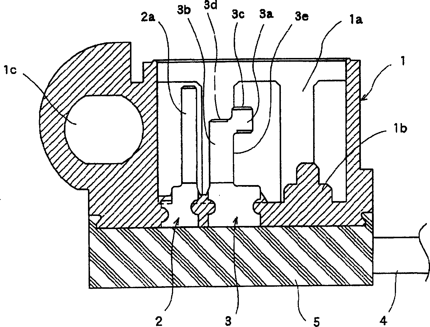
[0034] Below, use Figure 1 to Figure 8 An embodiment of the switch device of the present invention will be shown. figure 1 is a sectional view showing the switchgear of the present invention, figure 2 It is a sectional view of the main part viewed from a different direction of the switchgear, image 3 is the cross-sectional view of the shell, Figure 4 is a top view of the movable contact, Figure 5 is the front view of the movable contact, Figure 6 It is a cross-sectional view showing the state where the contact part for arc consumption is connected, Figure 7 It is a cross-sectional view showing the state where the contact part for switching is connected, Figure 8 It is a cross-sectional view showing a state disconnected from the contact part for arc consumption.

[0035] exist Figure 1 ~ Figure 3 Among them, the casing 1 is made of an insulating material such as synthetic resin, and is formed in a box shape with an open upper surface having a storage portion 1a...


PUM


Abstract

A switchgear that can cope with both high-load areas and micro-areas, is less prone to arc consumption at high loads, and can obtain stable contact. Formed on the movable contact (7) is a first contact portion (7b) in sliding contact with the common fixed contact (2), and a second and third contact portion (7c, 7d) in sliding contact with the individual fixed contact (3), On the single fixed contact (3) along the direction perpendicular to the lifting direction of the drive member (9), form the first contact portion (3c) for arc consumption that first contacts the second contact portion (7c), and then contacts with the second contact portion (7c). The 2nd contact part (3d) that the 3rd contact part (7d) contacts, the bottom side of the 2nd contact part (3d) is used as the sliding contact surface with the 3rd contact part (7d), at the same time the first contact part (3c ) is formed on the track of sliding contact with the second contact part (7c) on the lower surface side of the second contact part (7c).

Description

technical field [0001] The present invention relates to a vehicle-mounted switch device, and more particularly to a structure using a switch device for lighting when a door of an automobile is opened and closed. Background technique [0002] As the structure of the conventional switchgear, since it is necessary to switch the lamp load, a microswitch-type detection switch that can be used in a high-load area is used (for example, refer to Patent Document 1). [0003] Hereinafter, the configuration of a conventional microswitch type switch device for vehicles will be described with reference to the drawings. Figure 9 It is a sectional view showing the structure of a conventional microswitch type switchgear. [0004] exist Figure 9 Among them, the switch device consists of a base 52 and a cover 53 to form a housing 51 . Contacts 56 , 57 , 58 are inserted into the base 52 , and one end thereof protrudes outward to form connection contacts 60 , 61 , 62 . In addition, the cont...

Claims


Application Information

Patent Timeline
Patent Type & Authority Applications(China)
IPC IPC(8): H01H13/14H01H13/02H01H13/18H01H13/20H01H13/52
Inventor 武田昌之
Owner ALPS ALPINE CO LTD
Why Eureka
Try Eureka