Rotation support device for pinion shaft

A technology of pinion shaft and rotating support, which is applied in the direction of gear transmission, bearing assembly, rotating bearing, etc. It can solve the problems of increasing the size and difficulty in coping with the fuel consumption of automobiles, and achieves the prevention of excessive axial displacement, Securing the rigidity of the bearing and the effect of securing the axial rigidity

Inactive Publication Date: 2014-04-09
NSK LTD
View PDF7 Cites 0 Cited by
  • Summary
  • Abstract
  • Description
  • Claims
  • Application Information

AI Technical Summary

Problems solved by technology

In this structure, the load capacity can be increased compared with the case where a single row angular contact ball bearing is used as the rolling bearing on the side opposite to the pinion, but the reverse rotation torque (rotational resistance) will increase, so it is difficult to cope with automobile saving. fuel consumption requirements

Method used


Image

  • Rotation support device for pinion shaft
  • Rotation support device for pinion shaft
  • Rotation support device for pinion shaft

Examples


Embodiment

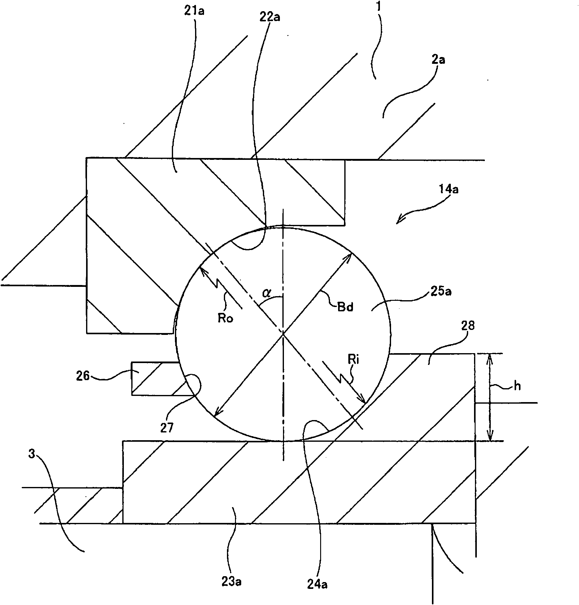
[0076] Next, refer to Figure 4-8 Experiments conducted to confirm the effects of the present invention will be described. First, an experiment conducted to obtain the relationship between the outer ring groove R ratio (Ro / Bd) and the dynamic torque will be described. In the experiment, 8 samples (contact angles are all 40°) with different values ​​of the outer ring groove R ratio in the range of 0.51 to 0.58 were used. 73mm 2 / s) Mineral oil, each sample was run under forced lubrication conditions. In addition, an axial load (2770N) was applied to each sample, and the rotational speed of the inner ring was 3000min. -1 . Figure 4 shows the results of the experiments performed in this way. by the Figure 4 From the experimental results shown, it is clear that the dynamic torque is sufficiently reduced when the outer ring groove R ratio is set to a value greater than 0.52.

[0077] Next, an experiment performed to obtain the relationship between the outer ring groove R r...


PUM


Abstract

Construction of a rotation support device for a pinion shaft is achieved that, together with being able to sufficiently maintain axial rigidity of a rolling bearing on the side opposite from the pinion gear side, it is able to sufficiently reduce the dynamic torque during operation and the starting torque at the start of operation. Together with using a single-row angular contact ball bearing 14a as the rolling bearing on the side opposite from the pinion gear side, the ratio of the radius of curvature Ro of the outer raceway 22a and the diameter Bd of the balls 25a (Ro / Bd) is regulated within the range 0.52 < Ro / Bd ‰¤ 0.56, and the contact angle ± is regulated within the range of 35° to 40°.

Description

technical field [0001] The present invention relates to a rotary support device for a pinion shaft constituting, for example, a differential device of an automobile or a transfer device of a four-wheel drive vehicle. Background technique [0002] A differential device of an automobile and a transfer device of a four-wheel drive vehicle generally have a structure including a pinion shaft provided with a pinion at one end, and the The pinion shaft is rotatably supported on the inner side of the housing so as to be able to support axial loads in both directions. [0003] Figure 9 The differential gear described in Patent Document 1 is shown in which the pinion shaft rotation support device of the first conventional structure is incorporated. The differential device is installed in the middle of the power transmission system of the car, and is used to vertically change the direction of rotation while reducing the rotational speed of the drive shaft. In this differential gear,...

Claims


Application Information

Patent Timeline
Patent Type & Authority Patents(China)
IPC IPC(8): F16C33/58F16C19/16F16C19/18F16H48/06
CPCF16C19/163F16C41/02F16C19/56F16H1/145F16C19/548F16C19/182F16C2240/76F16C2240/34F16C2240/46F16H2048/423F16C2240/70F16C19/505F16C2361/61
Inventor 田中孝道斋藤智治田上泰资
Owner NSK LTD
Why Eureka
Try Eureka