Coaxial line plug-in connection with integrated galvanic separation

A technology of plug connection and coaxial line, applied in the direction of connection device, two-part connection device, and parts of connection device, etc., can solve problems such as difficulty in equipment, and achieve the effect of small assembly cost

Inactive Publication Date: 2007-08-01
VEGA GRIESHABER GMBH & CO
View PDF7 Cites 0 Cited by
  • Summary
  • Abstract
  • Description
  • Claims
  • Application Information

AI Technical Summary

Problems solved by technology

Although it is possible to implement such a galvanic isolation configuration, it is very difficult to make this configuration inside the high-frequency module
Furthermore, it is particularly problematic that additional interference points occur in the signal path from the high-frequency module to the transmitting and receiving unit with this configuration

Method used


Image

  • Coaxial line plug-in connection with integrated galvanic separation
  • Coaxial line plug-in connection with integrated galvanic separation
  • Coaxial line plug-in connection with integrated galvanic separation

Examples


Embodiment Construction

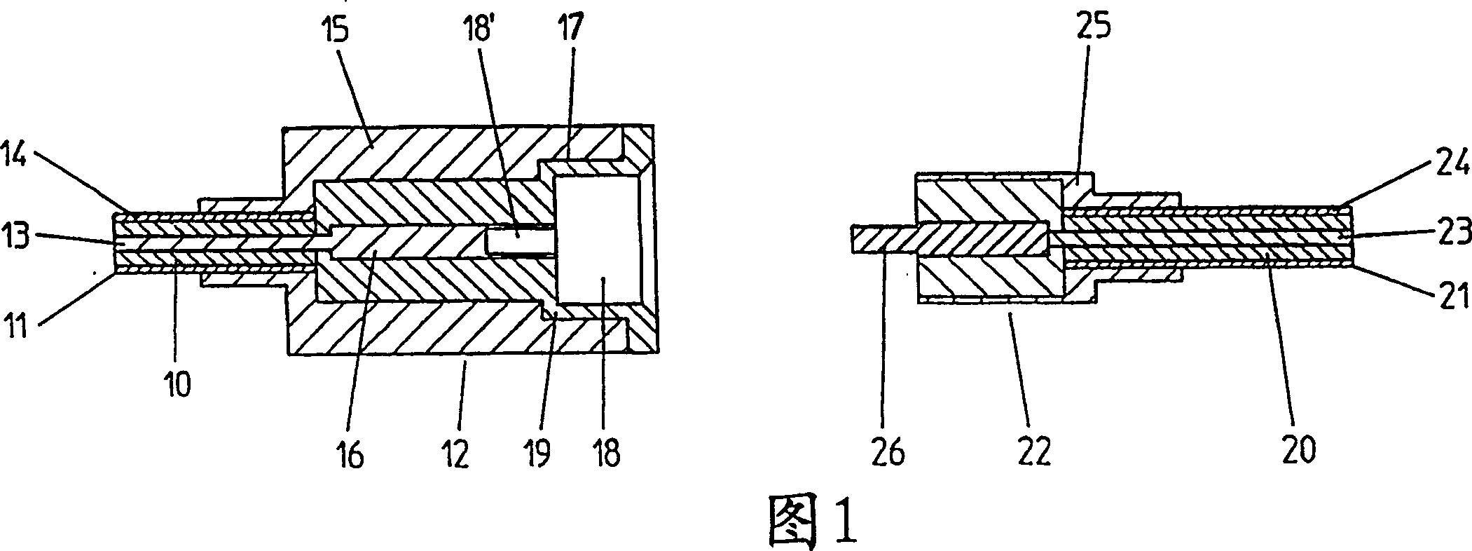
[0033] Fig. 1 is a longitudinal sectional view of a first embodiment of a plug connection according to the invention. The plug connection consists of a socket 12 and a plug 22 . Connected to the socket 12 is a coaxial line 11 which is connected to the transmitting and receiving unit. The coaxial line 11 consists of an outer conductor 14 as a shielded conductor and an inner conductor 13 for transmitting signals. The inner conductor 13 and the outer conductor 14 are insulated from each other by a dielectric 10 . The outer conductor 14 of the coaxial line is connected to the outer conductor of the socket 15 . The inner conductor of the coaxial line is connected to the inner conductor of the socket 16 .

[0034] The coaxial line 21 likewise consists of an inner conductor 23 for transmitting signals and an outer conductor 24 as a shielding conductor, which are insulated from each other by a dielectric 20 . The outer conductor 24 is connected to the outer conductor 25 of the plu...


PUM


Abstract

The invention relates to a plug-in connection for galvanically separating microwave signals in coaxial lines (11, 21) so as to meet the requirements of an explosion-proof separation. The plug-in connection comprises a plug (22) and a socket (12) with an inner conductor and an outer conductor (16, 26, 15, 25), both of which are connected to a coaxial line (11, 21) and are also provided with an inner conductor and an outer conductor (13, 23, 14, 24). The plug-in connection comprises a separating element (19) separating the outer conductor (15) of the socket (12) from the outer conductor (25) of the plug (22). In another embodiment of the invention, both the outer conductor (15, 25) and the inner conductor (16, 26) are galvanically separated.

Description

technical field [0001] The invention relates to a coaxial plug connection having an electrical isolation integrated therein. Such plug connections are used, for example, in liquid level detection technology. In order to transmit the microwave signal required for detecting the liquid level generated by a high-frequency module to a transmitting and receiving unit, such as a rod, horn or strip antenna, and to make the reflected The signal is sent back to an analyzer, preferably using coax. Background technique [0002] Such liquid level detection is required in almost all industrial sectors. In the chemical industry, for example, certain fillings of which the liquid level is subsequently determined consist of explosive dielectrics. In order to prevent explosions in or around the interior of containers or tanks during level detection, it is necessary to electrically separate conductors which may be at different potentials. Optionally, a separate potential equalization line c...

Claims


Application Information

Patent Timeline
Patent Type & Authority Patents(China)
IPC IPC(8): H01R13/646H01R13/52H01R13/02H01R13/7197H01R24/44
CPCH01R24/44H01R13/7197H01R13/025H01P5/026
Inventor 约瑟弗·费伦巴赫于尔根·莫策丹尼尔·舒尔特海斯
Owner VEGA GRIESHABER GMBH & CO
Why Eureka
Try Eureka