
Clock signal detection method and apparatus in electronic devices

A clock signal and electronic equipment technology, applied in the field of network communication, can solve the problems of inability to realize clock signal detection, poor universality of the detection circuit, and high cost

Active Publication Date: 2007-08-22
DATANG MOBILE COMM EQUIP CO LTD
View PDF8 Cites 2 Cited by
  • Summary
  • Abstract
  • Description
  • Claims
  • Application Information

AI Technical Summary

Problems solved by technology

When the detected clock frequency is low to a certain extent, even the detection of the clock signal cannot be realized
[0005] In addition, the design of the clock signal detection circuit using the clock vibration source method is relatively complicated and the cost is relatively high. Moreover, once the clock signal detection circuit is designed, it can only detect a clock signal of one frequency. It can only be realized by changing the design of the detection circuit, and the versatility of the detection circuit is poor

Method used


Image

  • Clock signal detection method and apparatus in electronic devices
  • Clock signal detection method and apparatus in electronic devices
  • Clock signal detection method and apparatus in electronic devices

Examples


Embodiment Construction

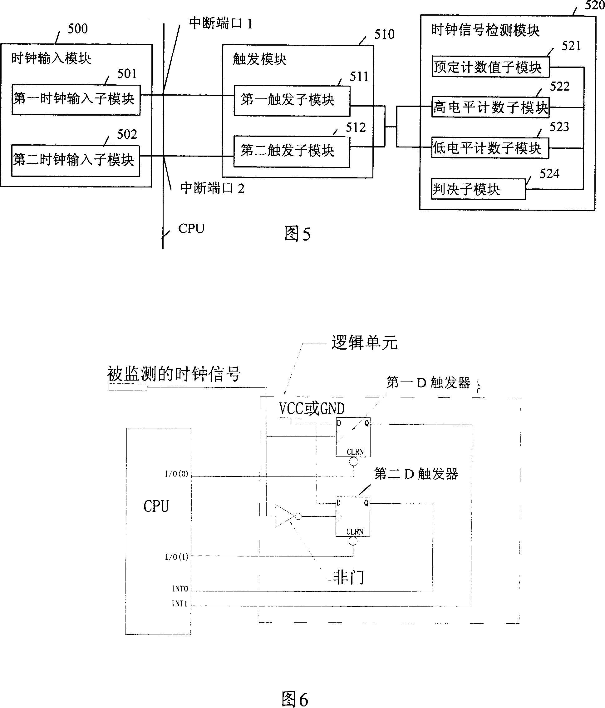
[0052] The core of the invention is to use the interrupt port of the CPU to realize the detection of the detected clock signal. Therefore, it is first necessary to determine the interrupt signal of the interrupt port of the CPU, then input the detected clock signal into the interrupt port of the CPU, and trigger the detection of the detected clock signal according to the determined interrupt signal. Perform clock detection.

[0053] The technical solution provided by the present invention will now be further described in detail in conjunction with the accompanying drawings.

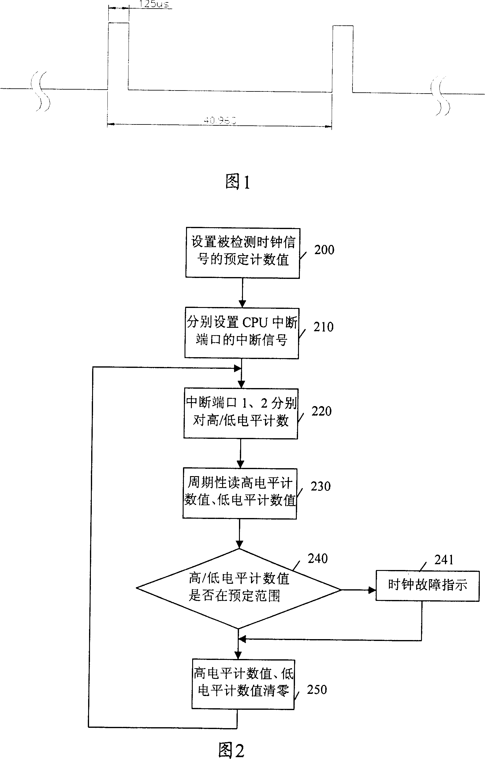
[0054] The flow chart of the clock signal detection method of the present invention is shown in FIG. 2 .

[0055] In FIG. 2, step 200, determine the clock frequency of the detected clock signal, and set the high-level predetermined count value and the low-level predetermined count value of the clock standard according to the clock frequency.

[0056]Go to step 210, respectively set the interrupt signals...


PUM


Abstract

This invention provides an electron device clock testing method, which comprises the following steps: determining the said CPU interval terminal signals and inputting the tested clock signal into the interval end of the said CPU; triggering the said tested clock signals for testing according to the interval signal. The invention provides an electron clock test device, which comprises clock input module, triggering module and clock signal test module.

Description

technical field [0001] The invention relates to the technical field of network communication, in particular to a clock signal detection method and device in electronic equipment. Background technique [0002] The clock is the basis for communication among various communication devices in the communication system. If the quality of the clock signal is poor or the clock signal is lost, digital information will be confused during the transmission process, and even the entire communication device will be in a state of paralysis. Therefore, it is very important in the communication system to ensure the reliability of the clock signal of the communication equipment and to detect the clock signal of the clock signal. [0003] At present, the method for detecting the clock signal is mainly: add a clock source to the circuit of the communication equipment, generate a clock signal from the clock source, and then use the method of frequency division to change the frequency of the clock...

Claims


Application Information

Patent Timeline
Patent Type & Authority Patents(China)
IPC IPC(8): H03K21/40H04L7/00
Inventor 刘飚何宇东
Owner DATANG MOBILE COMM EQUIP CO LTD
Learn More