
Distortion of front faceplate protected back projective TV set

A front panel and TV technology, applied in the direction of TV, color TV, color TV components, etc., can solve the problems of poor rigidity and easy deformation of the front panel, achieve enhanced rigidity, can be improved according to the degree, and improve the appearance of qualified rate effect

Inactive Publication Date: 2007-08-22
HISENSE +1
View PDF5 Cites 0 Cited by
  • Summary
  • Abstract
  • Description
  • Claims
  • Application Information

AI Technical Summary

Problems solved by technology

[0003] The purpose of the present invention is to solve the technical problem of poor rigidity of the front panel and easy deformation of the prior art, and provide a rear projection TV that prevents the deformation of the front panel, thereby greatly improving the deformation of the middle part of the panel

Method used


Image

  • Distortion of front faceplate protected back projective TV set
  • Distortion of front faceplate protected back projective TV set

Examples


Embodiment Construction

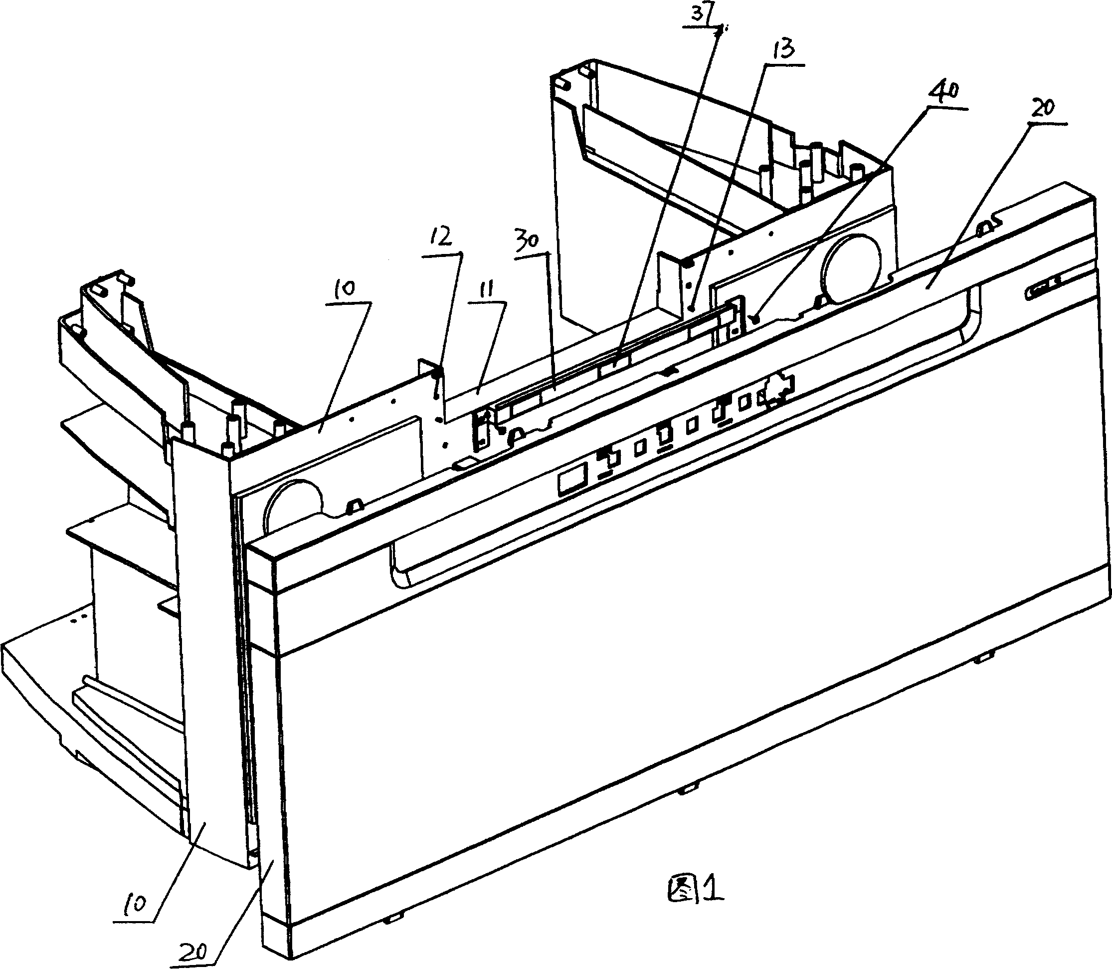
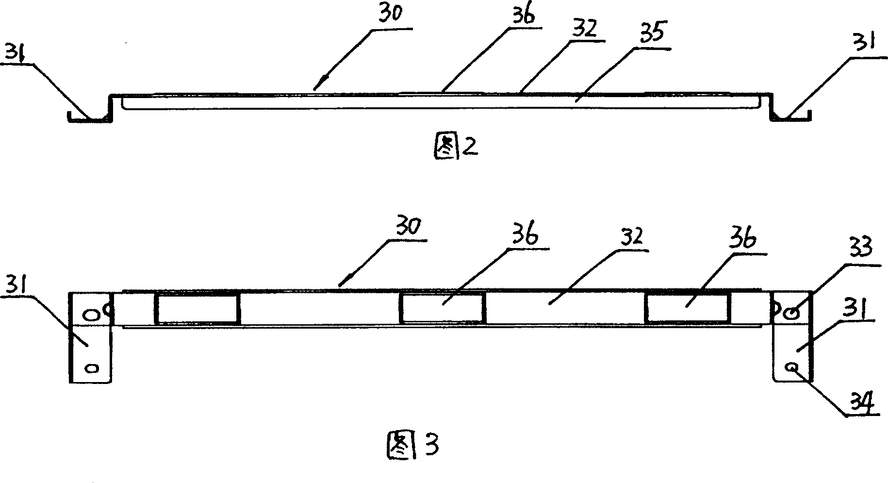
[0015] Referring to Fig. 1~Fig. 3, the present invention prevents the rear projection TV set of front panel from deforming and comprises the rear projection base of its bottom and the front panel fixed on the rear projection base. An inverted U-shaped sheet metal bracket that can support the front panel is fixed at the U-shaped groove of the base. The sheet metal bracket includes two side walls and a beam in the middle. Rigid flanging of the bracket; fixing holes and positioning holes are respectively opened on the two side walls, screw holes and positioning columns corresponding to the fixing holes and positioning holes are respectively provided on both sides of the U-shaped groove of the rear projection base, and the sheet metal bracket is inserted into the Fix the sheet metal bracket to the rear projection base with screws on the positioning posts on both sides of the U-shaped groove. There is also a positioning bump on the beam of the sheet metal bracket. Stickers are past...


PUM


Abstract

The invention includes base of back projector at bottom and front faceplate fixed on the base. U shaped trough is made on the middle of upper part of the base. Characters are that a sheet metal bracket in inverse U shape for supporting front faceplate is fixed on the said U-shaped trough; upper and middle parts of the front faceplate are fixed on the sheet metal bracket. By sheet metal bracket with good rigidity being added, the disclosed structure enhances rigidity of the front faceplate at middle part. The said projector provides large quantity of anti pressing on the front faceplate, and no happening ridgy distortion so as to raise acceptability for appearance of the front faceplate, and make users more satisfaction.

Description

technical field [0001] The invention relates to a rear projection TV set, in particular to a rear projection TV set which prevents deformation of the front panel. Background technique [0002] With the improvement of living standards, people's demand for home appliances is becoming more and more high-grade, and the market share of rear-projection TVs with their large screens is also increasing. Existing rear-projection televisions include a display screen, a rear-projection base below the display screen, and a front panel fixed on the rear-projection base. It is thin, which makes its rigidity very poor; and because there is a long U-shaped groove formed in the middle of the rear projection base, the front panel can only be fixed on both sides and the bottom of the rear projection base, and the middle part of the front panel is easy to bulge and deform. If the front panel is pressed slightly inward, the front panel will be displaced inward again, which seriously affects the ...

Claims


Application Information

Patent Timeline
Patent Type & Authority Patents(China)
IPC IPC(8): H04N5/64H04N5/74H04N9/31
Inventor 邵小军
Owner HISENSE
Learn More