Low profile electrical connector

A technology of electrical connectors and connectors, which is applied in the direction of connection, connection component installation, circuit, etc.

Inactive Publication Date: 2002-01-30
AVX CORP
View PDF3 Cites 4 Cited by
  • Summary
  • Abstract
  • Description
  • Claims
  • Application Information

AI Technical Summary

Problems solved by technology

However, the device requires a sufficient space between the boards to accommodate the connector housing and terminal housing

Method used


Image

  • Low profile electrical connector
  • Low profile electrical connector
  • Low profile electrical connector

Examples


Embodiment Construction

[0052] Referring now to one or more examples shown in the accompanying drawings, the presently preferred embodiments of the invention will be described in detail. Each example is provided by way of explanation of the invention, not limitation of the invention. For example, features shown or described as part of one embodiment can be used on another embodiment to yield a third embodiment. The present invention includes various modifications and changes that do not depart from the scope and spirit of the present invention.

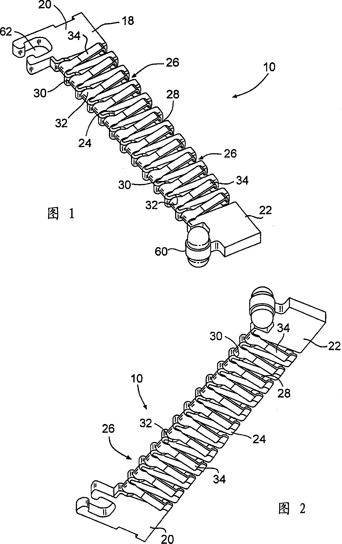
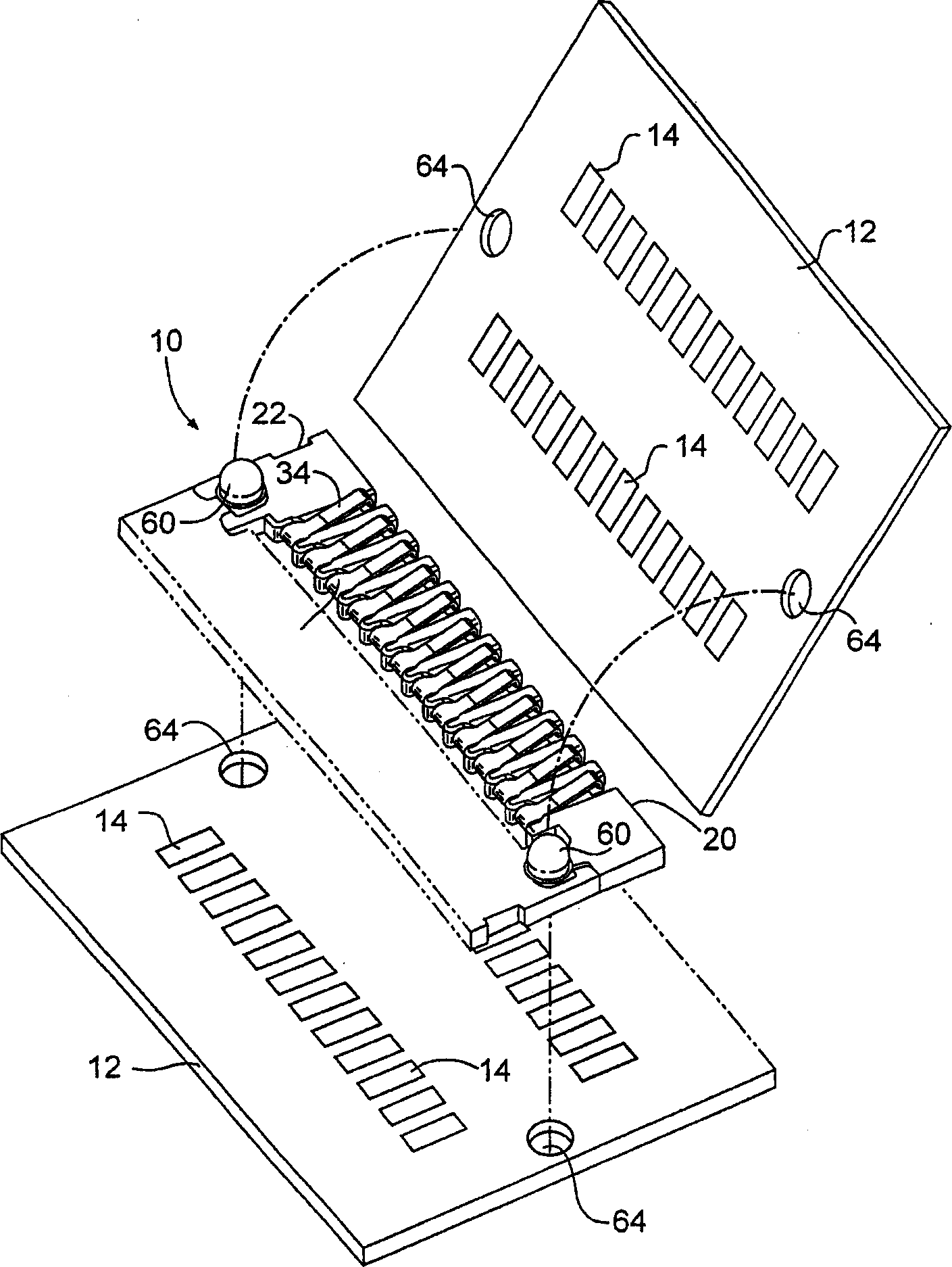
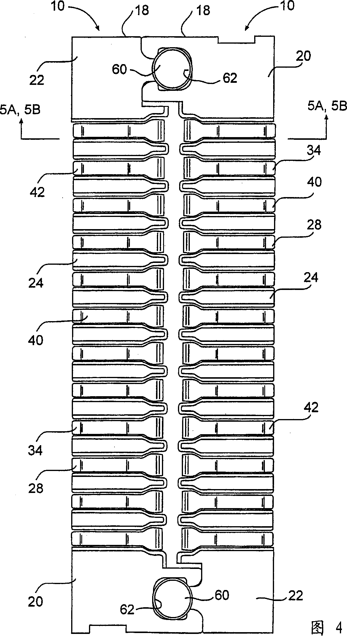
[0053] A typical preferred embodiment of a connector assembly according to the present invention is shown in the accompanying drawings, indicated generally at 10 . The connector assembly 10 is particularly useful in interconnecting facing conductive members (eg, circuit boards) in a stacked configuration and minimizing the stack height between the conductive members. For ease of illustration and description, the conductive component is represented and refe...


PUM


Abstract

A thin profile electrical connector includes an insulating body member having a longitudinally extending leg defined between opposite ends. A plurality of adjacently disposed and spaced apart connector elements are mounted on the longitudinal leg, for example within recesses or grooves defined transversely to the longitudinal leg. Each connector element includes a closed end and an open end defined by extending arms. The closed end wraps around the longitudinal leg at each connector position. Each connector element includes outwardly facing contact surfaces defined on each of the extending arms for mating contact with respective pads of separate facing circuit boards.

Description

technical field [0001] The present invention relates to electrical connectors, and more particularly to electrical connectors for interconnecting electronic assemblies, such as printed circuit boards, which are intended to be mounted adjacent to each other in a generally vertical stacked configuration. Background technique [0002] Prior art methods of interconnecting electronic components, particularly circuit boards, are well known. For example, it is known to hardwire the circuit boards together, or to use edge connectors carried by the circuit board which engage mating fixed edge connectors housed within the frame in which the circuit board is mounted. [0003] A concern with traditional board-to-board connectors is the limited space for board or component connections within electronic devices. For a traditional connector that uses multiple terminals arranged laterally in the housing at a certain distance, one contact arm of each terminal is soldered to the circuit pa...

Claims


Application Information

Patent Timeline
IPC IPC(8): H01R12/71H01R13/24H01R13/73
CPCH01R13/24H01R12/714
Inventor 彼得·G·比晓普戴维·E·里平顿
Owner AVX CORP
Why Eureka
Try Eureka