Fuel-jetting device

A fuel injection device and injection hole technology, which can be applied to fuel injection devices, special fuel injection devices, fuel injection devices with wear reduction measures, etc., can solve problems such as poor durability, and achieve the effect of overall compactness and light stress concentration.

Inactive Publication Date: 2002-02-27
DENSO CORP
View PDF1 Cites 0 Cited by
  • Summary
  • Abstract
  • Description
  • Claims
  • Application Information

AI Technical Summary

Problems solved by technology

A branched fuel conduit with such an acute border has the disadvantage of being relatively less durable

Method used


Image

  • Fuel-jetting device
  • Fuel-jetting device
  • Fuel-jetting device

Examples


Embodiment Construction

[0021] (first embodiment)

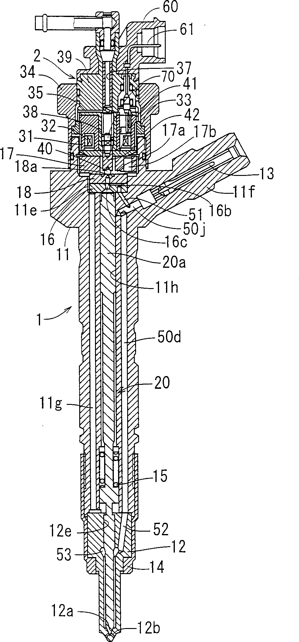
[0022] Refer below figure 1 and 2 The injector 1 as the fuel injection device according to the first embodiment is described. The injector 1 is inserted and mounted on an engine head of an engine (not shown), and directly injects high-pressure fuel supplied from a common rail (not shown) into each cylinder of the engine.

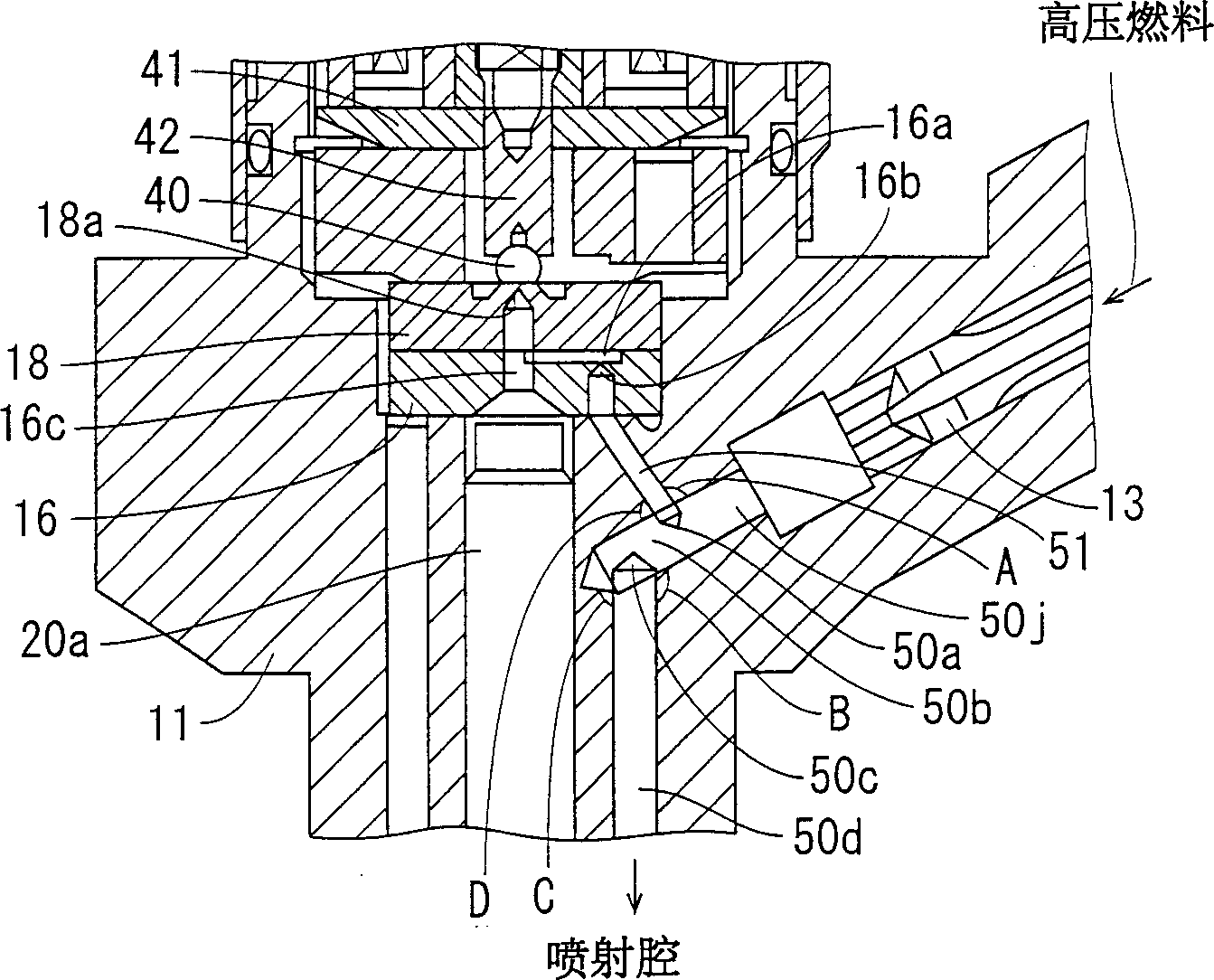
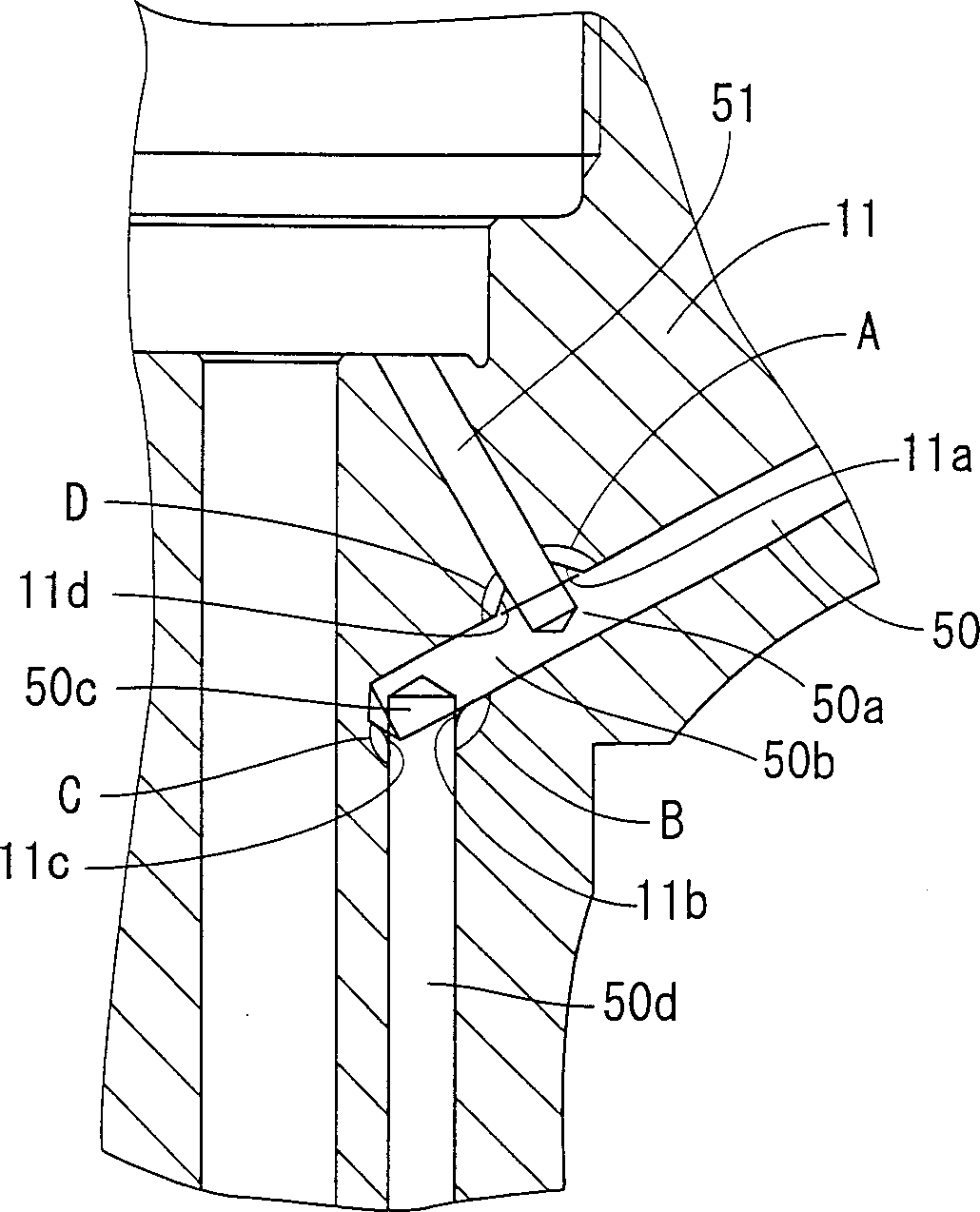
[0023] A holder body 11 is provided with a needle housing hole 11h for slidably receiving a nozzle valve member (valve member) 20 . The holder body 11 is also provided with an inlet portion 11f extending to the central axis of the holder body 11 at an angle of 61.5°. A rod filter 13 is arranged in the inlet portion 11f. The holder body 11 is provided with a vertical hole 50d at a position radially outward of the needle valve receiving hole 11h. The upper end of the vertical hole 50d communicates with a first inclined hole 50j formed in the inlet portion 11f. The lower end of the vertical hole 50d opens on the lower end surfa...


PUM


Abstract

In a Fuel-jetting device, a first fuel duct (50j) using for connecting one intake to a jet chamber (53) extends aslope relatively to the valve case (12) to the a bending portion (50c) from the intake, and then runs out to the jet chamber from the bending portion. A second fuel duct (51) starts deriving from the first duct at the first component (50), using for connecting the intake to the control chamber (16c). The angle (B, C) where the wall surface of the first liquid duct forms at bending portion of each wall boundary and the angle (A, D) where the wall surface of the first and second fluid duct forms at the component of each wall boundary are all 90 DEG or the above, and each straight portion (50b) is between the component and the bending portion.

Description

field of invention [0001] The present invention relates to a fuel injection device, particularly suitable for such a fuel injection device in which high-pressure fuel accumulated in a common rail is injected into a combustion chamber. Background technique [0002] Common-rail type fuel injection devices, in which high-pressure fuel accumulated in a common rail is injected into combustion chambers, are well known. The common rail fuel injection device has a control chamber for applying fuel pressure to the valve member in the direction of valve closing and an injection chamber for applying fuel pressure to the valve member in the direction of valve opening. Injection timing is controlled by adjusting the fuel pressure in the control chamber. In a conventional common rail type fuel injection device as disclosed in JP-A-9-158811, high-pressure fuel introduced from an inlet is distributed into a control chamber and an injection chamber through branch conduits. The branch condu...

Claims


Application Information

Patent Timeline
IPC IPC(8): F02M47/00F02M47/02F02M55/00F02M55/02F02M61/16F02M61/20
CPCF02M61/168F02M47/027F02M2200/04F02M2200/02F02M2200/8069F02M55/00F02M55/02
Inventor 永井光一都筑祥博
Owner DENSO CORP
Why Eureka
Try Eureka