

Two-way velve
A technology of two-way valves and bonnets, applied in the direction of valve details, diaphragm valves, valve devices, etc., can solve problems such as unsatisfactory applicability, difficulty in changing pipes freely, and difficulty in connecting pipes to control ports, etc.
- Summary
- Abstract
- Description
- Claims
- Application Information
AI Technical Summary
Problems solved by technology
Method used
Image

Examples
Embodiment Construction
[0010] Description of the preferred embodiment
[0011] One embodiment of the two-way valve will be described below with reference to the drawings.
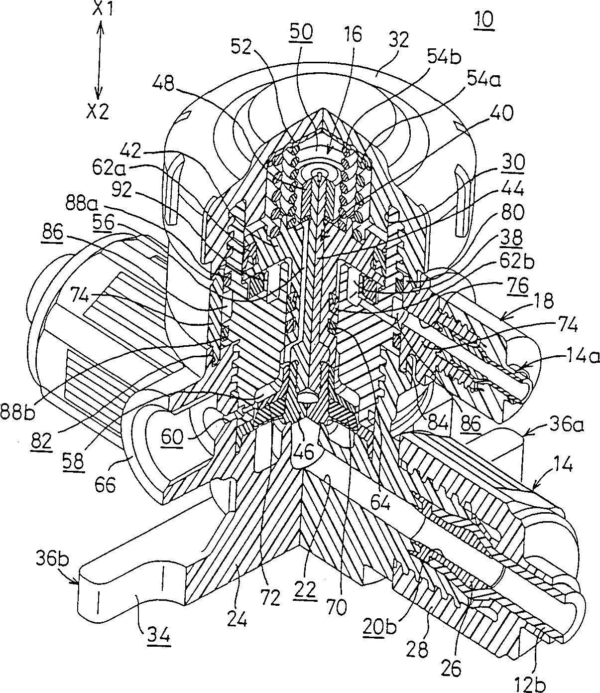
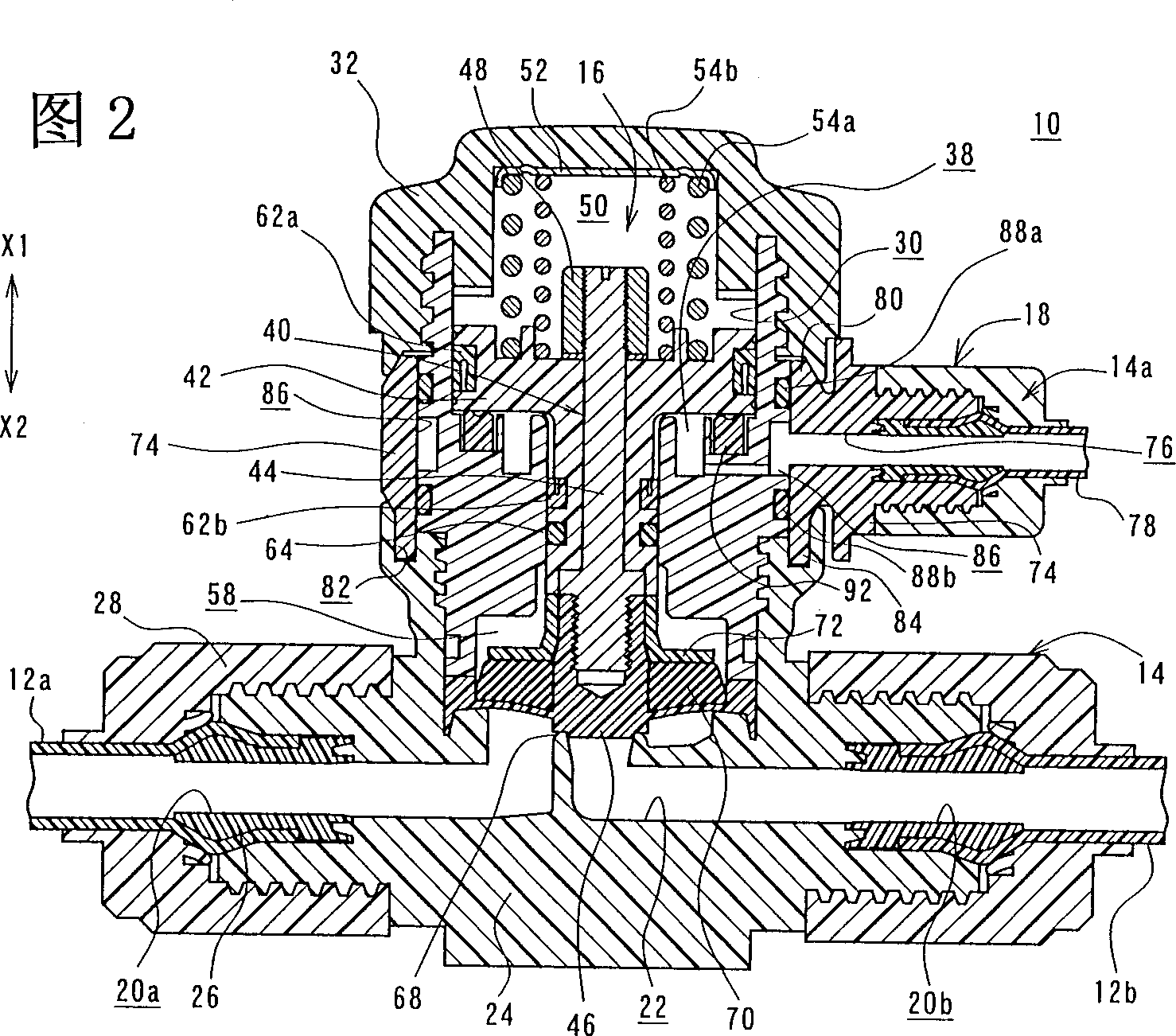
[0012] in figure 1 In and 2, reference numeral 10 denotes a two-way valve according to an embodiment of the present invention.
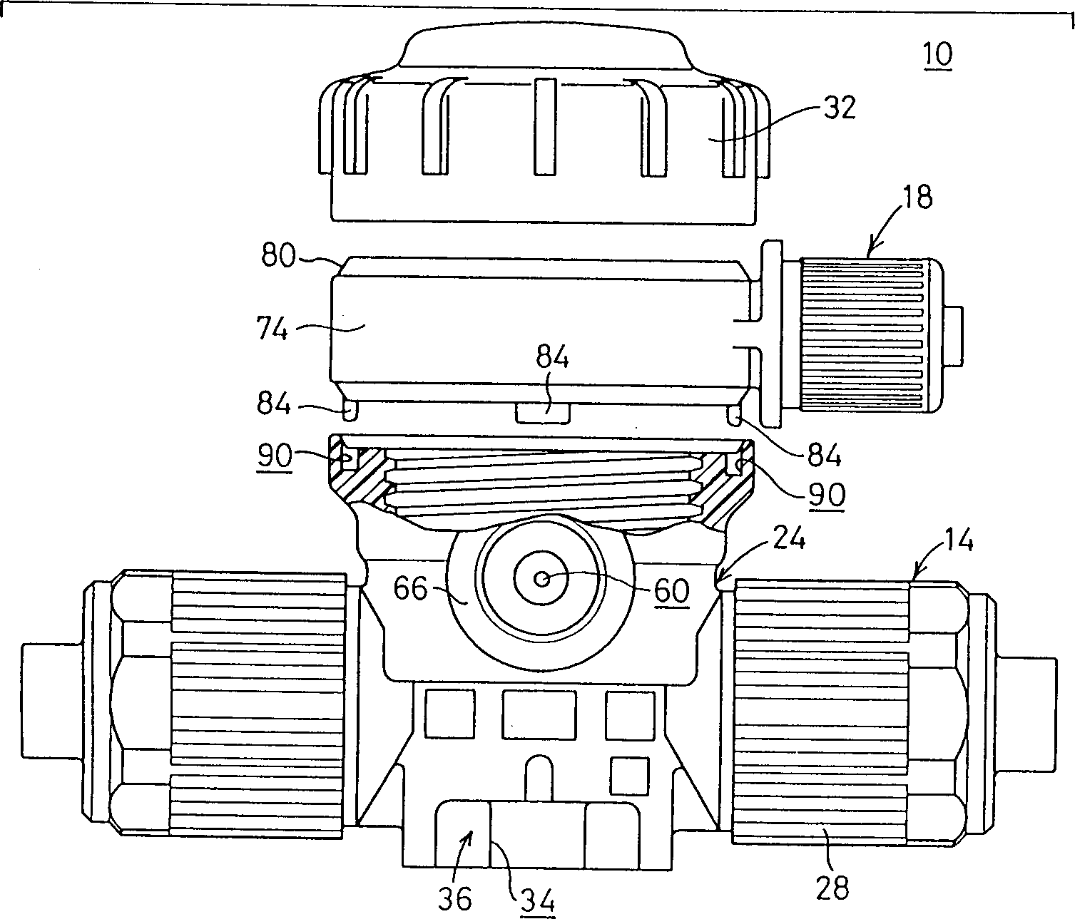
[0013] The two-way valve mainly includes a connecting part 14 detachably mounted on a pair of tubes 12a and 12b, a valve mechanism 16 placed above the connecting part, and a control pressure supply part for supplying control pressure to activate the valve mechanism 16. 18.
[0014] The connecting part 14, the valve mechanism 16, and the control pressure supply part 18 are assembled into a whole.
[0015] As shown in FIG. 2, the connecting portion 14 has a first opening 20a and a second opening 20b on opposite ends thereof, respectively. In addition, the connecting part 14 includes a body 24, a pair of inner members 26 and a pair of lock nuts 28. The body 24 has a fluid passage 22 defined in its interior to...
PUM
 Abstract
Description
Claims
Application Information