Image scanner

A scanner and image technology, applied in the field of image scanners, can solve problems such as the inability to solve the friction of transparent scanning platforms

Inactive Publication Date: 2005-03-02
YUDONG PLASMA TECH
View PDF1 Cites 1 Cited by
  • Summary
  • Abstract
  • Description
  • Claims
  • Application Information

AI Technical Summary

Problems solved by technology

However, it still cannot solve the defect of friction betwe

Method used


Image

  • Image scanner
  • Image scanner
  • Image scanner

Examples


Embodiment Construction

[0048] In order to improve the defects of the above-mentioned commonly used image scanners, the present invention mainly develops an image scanner with a wireless transmission function, which is used to save the setting of the commonly used flexible cable 14 and the signal line 16, and then achieve the main purpose of the present invention .

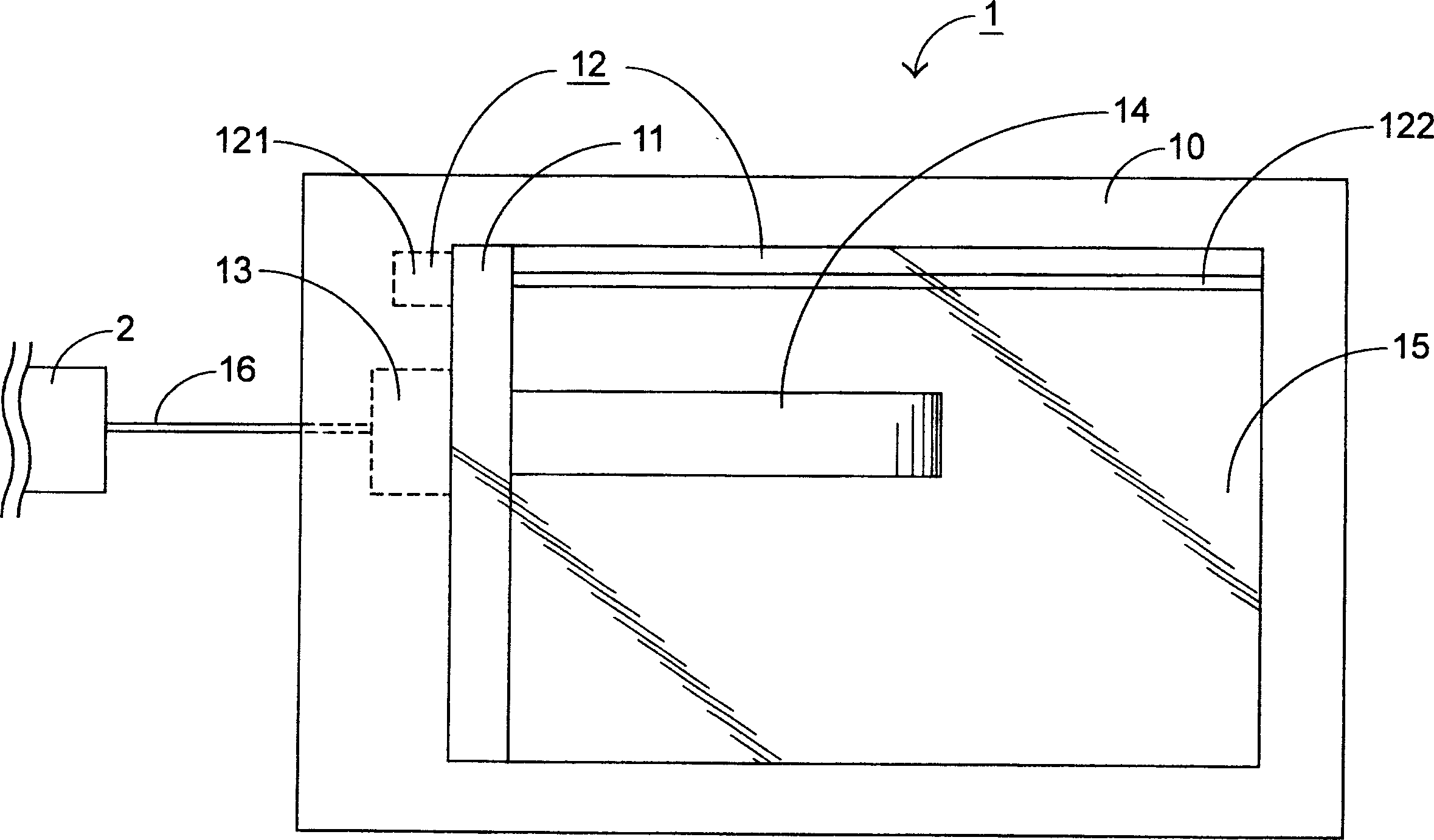
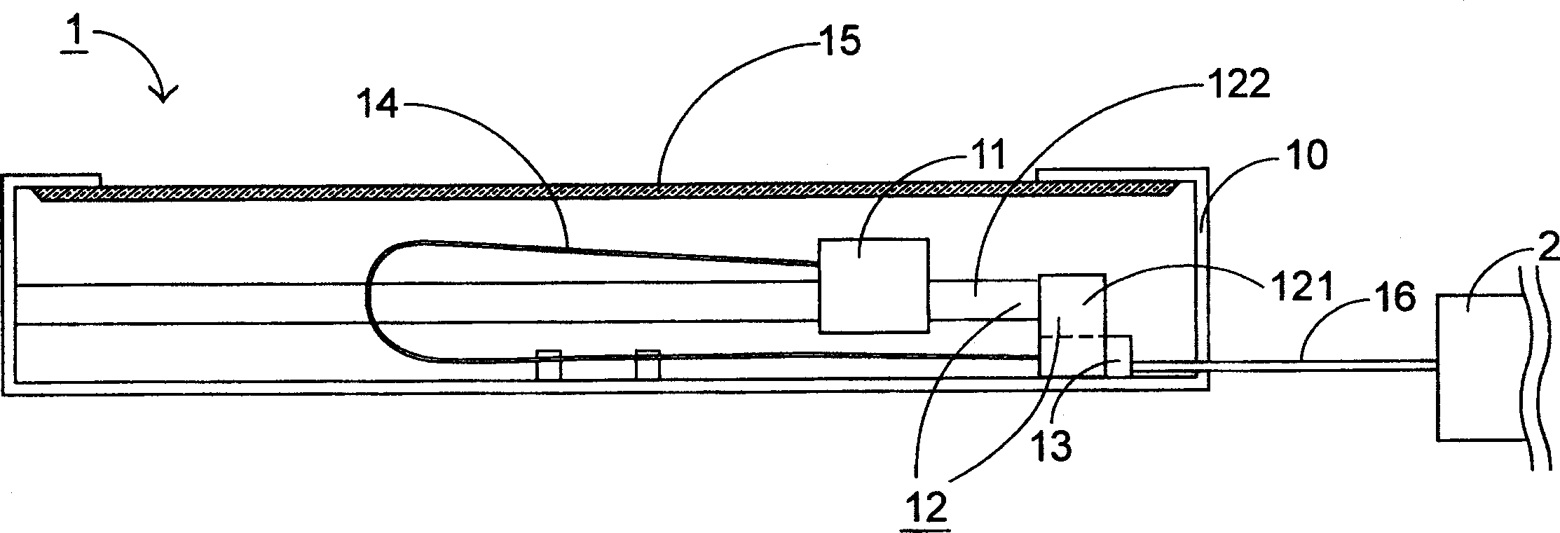
[0049] Please refer to FIG. 3(A), which is a schematic structural diagram of a first preferred embodiment of the flatbed image scanner 5 of the present invention, which discloses a computer system 2, a universal serial bus 21, a wireless signal receiving device 3, A flatbed image scanner housing 51 , a first elongated metal rod 52 , a second elongated metal rod 53 , an optical-mechanical module 54 , and a wireless signal transmitting device 7 . When the power of the first flatbed image scanner 5 is turned on, a voltage difference can be provided between the first elongated metal rod 52 and the second elongated metal rod 53, and the elong...


PUM


Abstract

This invention relates to an image scanner used between a computer system and a scan object including: an optical computer module for converting the image of the object to digital image data, a radio signal emit device integrated to the optical computer module receiving the digital image data and modulating it to a radio signal to be transmitted and a radio signal receiving device set outside of the module and connected on the computer system receiving said radio signal to be demodulated to digital image data and input to said computer system.

Description

technical field [0001] The invention relates to an image scanning device, in particular to an image scanner for transmitting image information with wireless signals. Background technique [0002] Flat flexible cable (FFC) is a commonly used connecting cable in electronic devices, and it is used in situations where the relative distance between two electronic products is likely to change and a large amount of data transmission is required. In a flatbed scanner, the optical-mechanical module that moves back and forth for scanning and its control circuit is such a situation, and the optical-mechanical module is connected to the control circuit through a flexible cable. [0003] Please refer to FIGS. 1(A) and (B), which are schematic top and side cross-sectional views of a flatbed scanner 1, respectively. The flatbed scanner 1 generally includes a casing 10 , an optical-mechanical module 11 , an optical-mechanical module driving mechanism 12 , a control circuit 13 and a flexibl...

Claims


Application Information

Patent Timeline
IPC IPC(8): G06F13/00H04B5/02H04N1/04
Inventor 陈锡裕沈功卓林宏泽
Owner YUDONG PLASMA TECH
Why Eureka
Try Eureka