Camera calibration method and measurement method based on binocular measurement device

A technology of measuring device and calibration method, which is applied in image communication, image analysis, image data processing and other directions, can solve the problems of wearable near-eye display equipment that cannot be used normally, unfavorable for users to use for a long time, and poor effect.

Pending Publication Date: 2020-10-27
SHENZHEN HUYNEW TECH CO LTD
View PDF0 Cites 2 Cited by
  • Summary
  • Abstract
  • Description
  • Claims
  • Application Information

AI Technical Summary

Problems solved by technology

[0003] For example, when the combined image effect of the two monocular optical modules of the wearable near-eye display device is beyond the acceptable range of the user, the user will feel that the images of the left and right eyes cannot overlap, which will cause the wearable near-eye display device to malfunction. use; and when the combined image effect of the two monocular optical modules of the wearable near-eye display device is within the acceptable range of the user but the effect is poor, it is easy to cause the user's visual fatigue, which is not conducive to the user's long-term use

Method used


Image

  • Camera calibration method and measurement method based on binocular measurement device
  • Camera calibration method and measurement method based on binocular measurement device
  • Camera calibration method and measurement method based on binocular measurement device

Examples


Embodiment 1

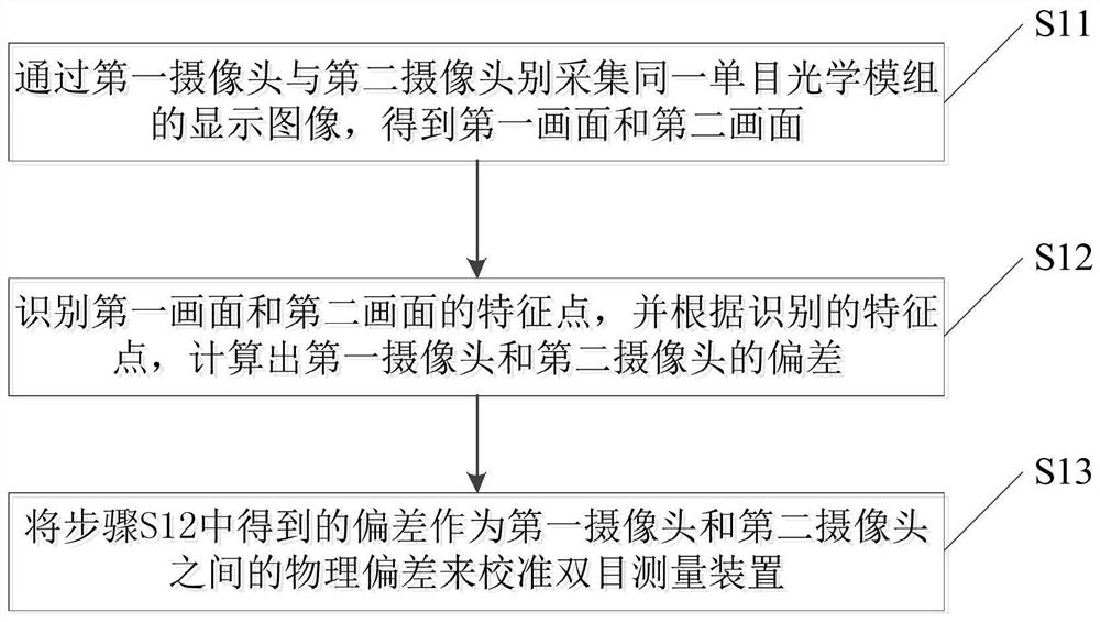
[0059] The binocular measurement device includes a first camera and a second camera. Reasons for the deviation between the first camera and the second camera include: the deviation of the image sensors of the two cameras themselves, and the fact that the optical axes of the two cameras cannot be absolutely completely parallel due to the assembly process. So no matter what, there will always be a physical offset between the two cameras. In the following, the camera calibration method will be specifically described through an embodiment.

[0060] Please refer to the attached figure 1 , In this embodiment, a camera calibration method is provided, which is used to calibrate a binocular measuring device, so as to eliminate the problem of the binocular camera of the binocular measuring device measuring the suitability of an AR / VR wearable near-eye display device equipped with a binocular module. The physical deviation in the image level can improve the feasibility and accuracy of ...

Embodiment 2

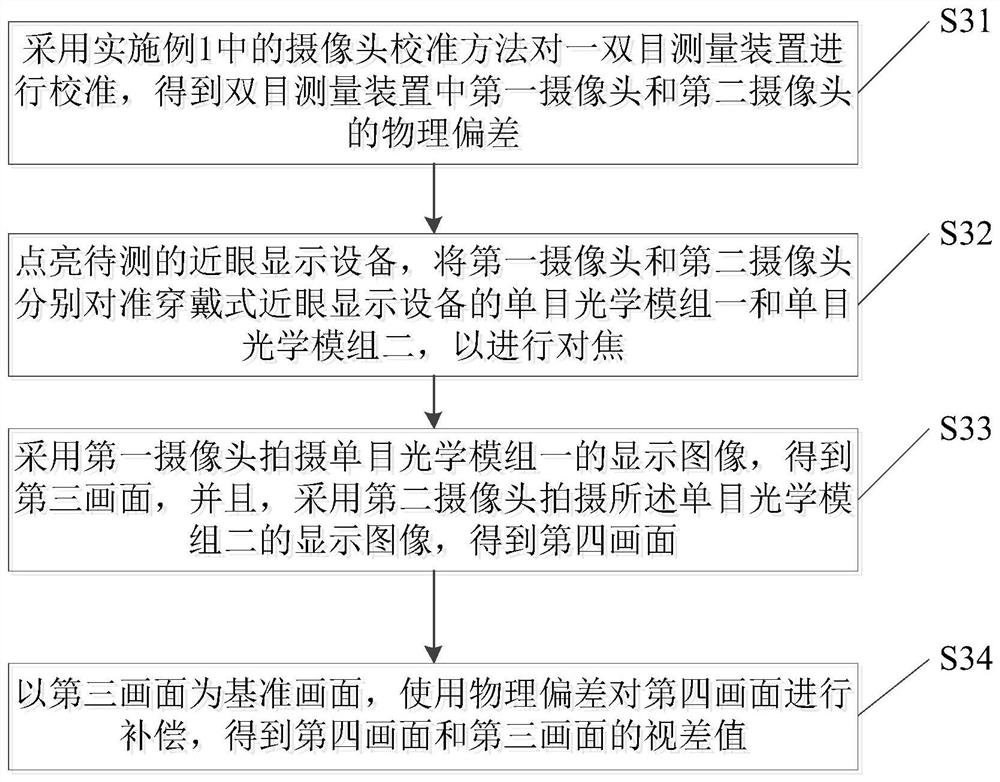
[0092] Please refer to the attached image 3 , based on the camera calibration method in Embodiment 1 above, this embodiment also provides a measurement method based on a binocular measurement device, which is used to measure the optical parameters of the wearable near-eye display device to be tested through the binocular measurement device. The binocular measurement device includes a first camera and a second camera, and the wearable near-eye display device to be tested includes a monocular optical module 1 and a monocular optical module 2. The optical parameter measurement method includes the following steps:

[0093] Step S31: Using the camera calibration method in Embodiment 1 to calibrate a binocular measuring device to obtain the physical deviation between the first camera and the second camera in the binocular measuring device.

[0094] In this step, for the method of obtaining the physical deviation between the first camera and the second camera, reference may be made ...

Embodiment 3

[0138] This embodiment also provides a binocular measurement device, the binocular measurement device is the binocular measurement device used in the calibration of the camera calibration method in the above embodiment 1, and is a binocular measurement based on the embodiment 2 The binocular measuring device that adopts during the measuring method of device, its structural feature is corresponding with each feature of embodiment 1 and implementation 2.

[0139] Among them, the binocular measurement device of this embodiment can be used to measure the degree of image cohesion of the wearable near-eye display device 1 with two monocular optical modules, and of course can also measure other optical parameters of the near-eye display device 1, such as distortion.

[0140] Such as Image 6 As shown, the compact binocular measurement device includes an integrated binocular camera 3 , a data calculation module 33 connected to the integrated binocular camera 3 , and a display componen...


PUM


Abstract

The invention discloses a camera calibration method and a measurement method based on a binocular measurement device. The calibration method comprises the following steps: respectively acquiring display pictures of the same monocular optical module through two cameras, and calculating a deviation between the two display pictures according to feature points at the same positions of the two displaypictures to serve as a physical error between a first camera and a second camera; the physical deviation is used for a binocular measuring device to measure compensation of optical parameters of the wearable near-to-eye display device, and finally the parallax value of the two monocular optical modules of the wearable near-to-eye display device to be measured is obtained. The method is simple andeasy to implement, the binocular camera can be quickly measured and calibrated, and the optical parameters, such as the image combination degree, of the wearable near-to-eye display equipment can be quickly measured, so that more comfortable use experience is provided for a user.

Description

technical field [0001] The invention relates to the detection field of wearable near-eye display equipment, in particular to a camera calibration method and a measurement method based on a binocular measurement device. Background technique [0002] Whether the optical parameters of the two monocular optical modules of wearable near-eye display devices such as Virtual Reality (VR) and Augmented Reality (AR) meet the standards is the best way to measure whether the product can provide users with sufficient comfort. One of the important indicators. [0003] For example, when the combined image effect of the two monocular optical modules of the wearable near-eye display device is beyond the user's acceptable range, the user will feel that the images of the left and right eyes cannot overlap, which will cause the wearable near-eye display device to fail to work normally. use; and when the combined image effect of the two monocular optical modules of the wearable near-eye display...

Claims


Application Information

Patent Timeline
Patent Type & Authority Applications(China)
IPC IPC(8): G06T7/55G06T7/73H04N17/00
CPCG06T7/55G06T7/74H04N17/002
Inventor 朱建雄李潇张韦韪
Owner SHENZHEN HUYNEW TECH CO LTD
Why Eureka
Try Eureka