Unsprung third rail collector beam support for a swing arm primary suspension railway truck

A technology for railway wagons and collector rings, which is applied to railway vehicles, electric tracks, locomotives, etc., and can solve problems such as insufficient beam elastic pads

Inactive Publication Date: 2002-03-13
BUCKEYE STEEL CASTINGS CO
View PDF0 Cites 2 Cited by
  • Summary
  • Abstract
  • Description
  • Claims
  • Application Information

AI Technical Summary

Problems solved by technology

[0005] However, on truck underframes equipped with swing arm primary suspensions, simple elastic pads at each end of the b

Method used


Image

  • Unsprung third rail collector beam support for a swing arm primary suspension railway truck
  • Unsprung third rail collector beam support for a swing arm primary suspension railway truck
  • Unsprung third rail collector beam support for a swing arm primary suspension railway truck

Examples


Embodiment Construction

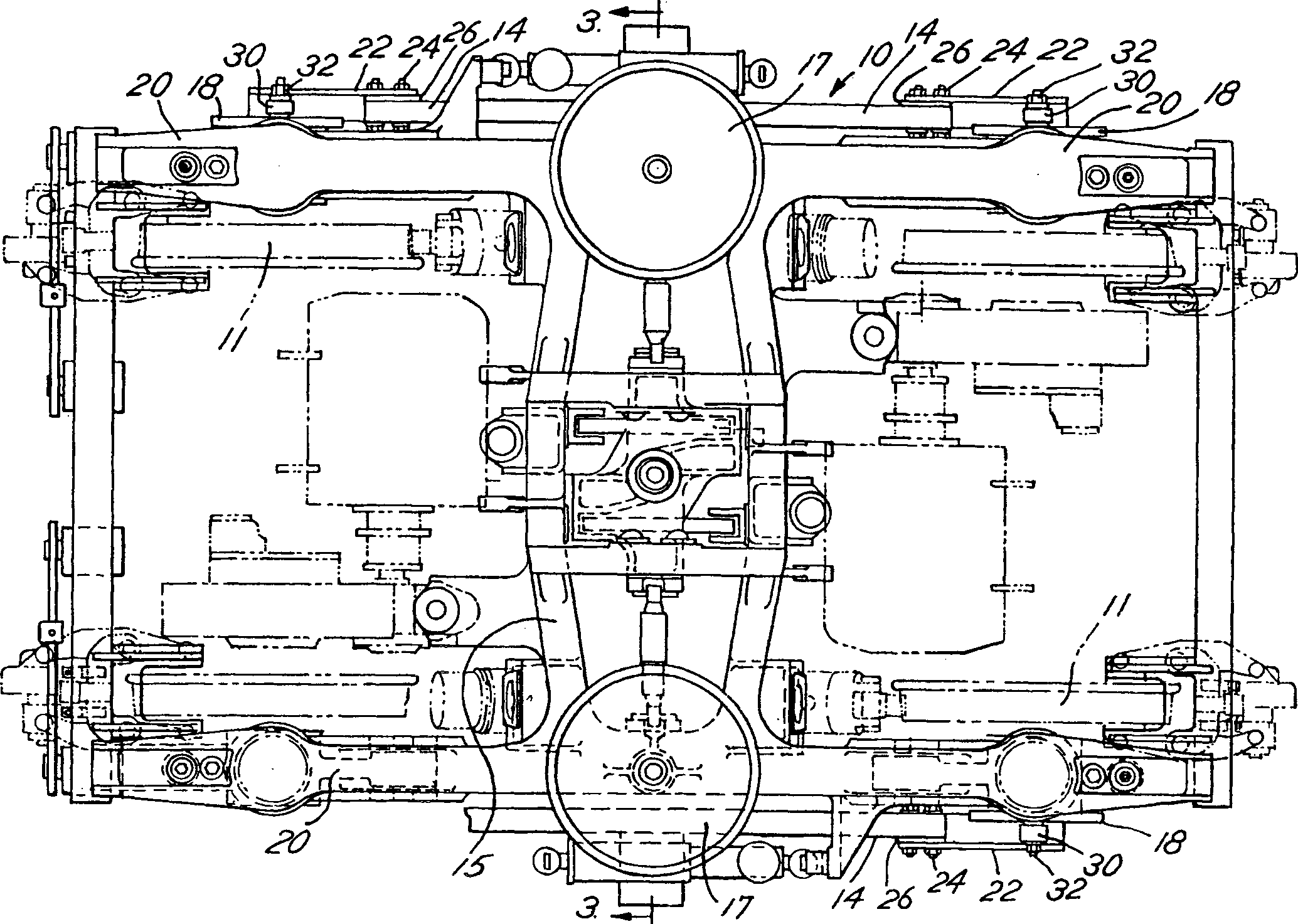
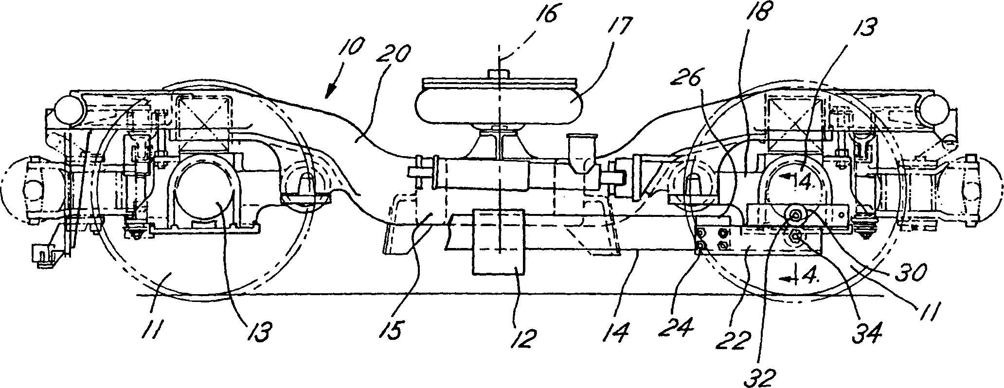
[0016] refer to Figure 1-3 , shows a preferred embodiment of the electric railway wagon underframe of the present invention equipped with a preferred third rail collector beam support, as conventional, the electric wagon underframe 10 includes the wheelsets, It comprises two wheels 11 spaced transversely from each other and connected by a transversely extending axle 13 . Supported on each wheel set is the truck underframe frame 20 on which the secondary suspension 17 is mounted.

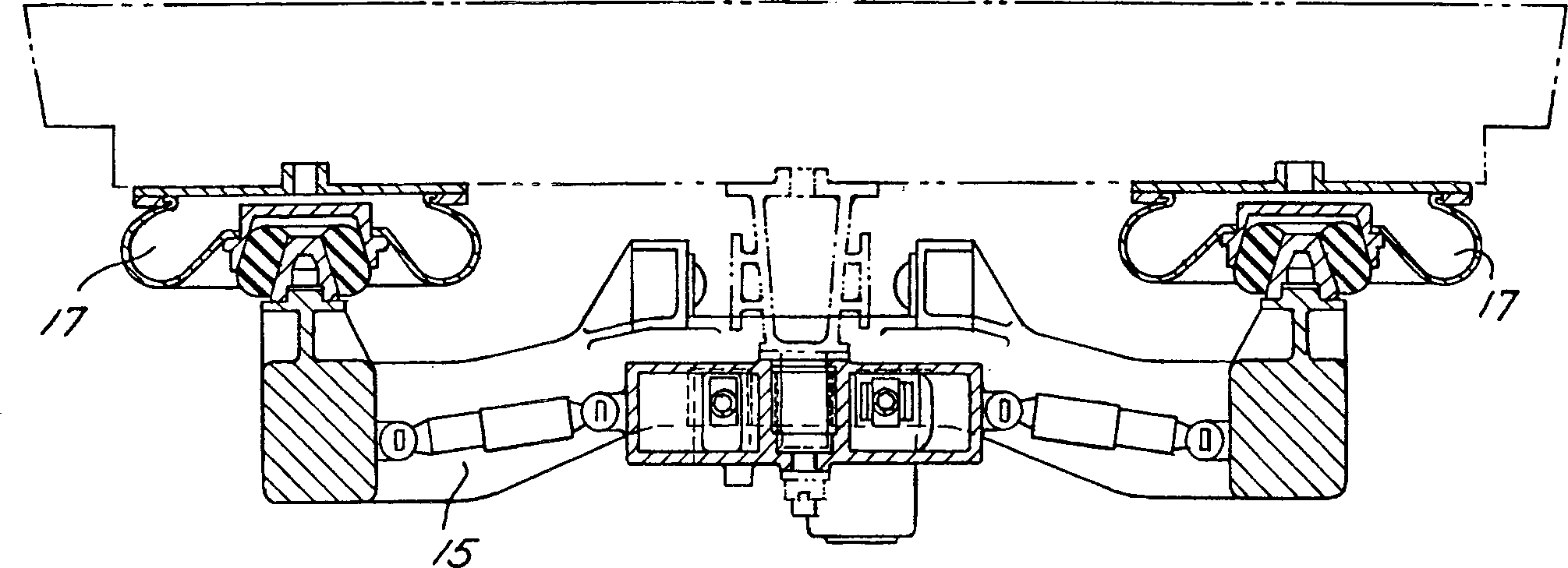
[0017] The preferred electric truck chassis 10 also includes a slip ring 12 , shown generally, mounted on a non-conductive slip ring beam 14 at or near a truck bed centerline 16 . A slip ring 12 is mounted on each side of the truck chassis 10 . Slip ring 12 is typically a brake shoe or plate that runs against the charged third along-line track and receives current from the charged track. The slip ring beam 14 extends longitudinally from the truck underframe centerline 16 to adjacent the swing arm...


PUM


Abstract

An electric railway truck (10) comprises an unsprung third rail collector beam (14) for a swing arm primary suspension. The collector beam (14) and attached current collector (12) are mounted to the truck frame (20) through the use of mounting adapters (22), links (30), and elastomeric bushings (28). Specifically, in the vicinity of the swing arm axle housings (18), the collector beam (14) is secured to the mounting adapters (22) which, in turn, are suspended below the respective axle housings (18) by the links (30) and accompanying elastomeric bushings (28). The torsional deflection of the elastomeric bushings (28) permit the links (30) to swing in the longitudinal direction, thereby accommodating the relatively larger angular and longitudinal axle housing motions created by a swing arm primary suspension.

Description

technical field [0001] The present invention relates generally to an electric railway truck chassis, and in particular to a collector beam for an electric railway truck chassis fitted with a swing arm primary suspension. Background technique [0002] Self-propelled electric railway wagon undercarriages require a means to transmit remotely generated electrical power from a third track along the line to the traction motors mounted on the wagon undercarriage. One traditional way of accomplishing this transfer is through the use of slip rings mounted on the railway wagon chassis. The slip ring is fitted with brake shoes or rams which run against the charged along-line third rail which is usually installed near the foundation on the outside of the running rail. Current from the charging third rail flows from the slip ring's brake shoes or rams to the traction motor. [0003] It is highly desirable to minimize the relative movement between the slip ring an...

Claims


Application Information

Patent Timeline
IPC IPC(8): B60L5/38B60M1/30B61F5/26
CPCB60L2200/26B61F5/26B60M1/30B60L5/38
Inventor 理查德·B·波利
Owner BUCKEYE STEEL CASTINGS CO
Why Eureka
Try Eureka