Rope drag chain

A traction chain and cable technology, applied in the field of cable traction chain, can solve the problems of easy wear and plastic powder production

Inactive Publication Date: 2002-04-10
TSUBAKIMOTO CHAIN CO
View PDF0 Cites 5 Cited by
  • Summary
  • Abstract
  • Description
  • Claims
  • Application Information

AI Technical Summary

Problems solved by technology

[0006] Further, during the use of the energy delivery catheter stent, the inner tube part made of synthetic resin is easily worn due to friction with the half body of the outer tube part made of metal, and plastic powder is generated

Method used


Image

  • Rope drag chain
  • Rope drag chain
  • Rope drag chain

Examples


Embodiment Construction

[0028] The following description is merely explanatory in nature and is not intended to limit the invention or its application and uses in any way.

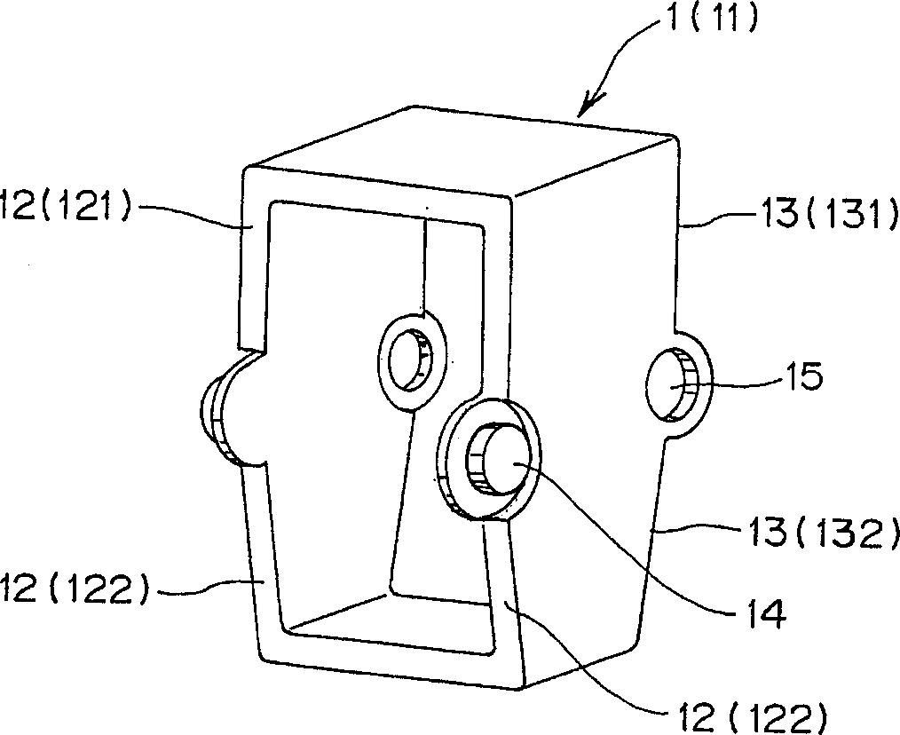
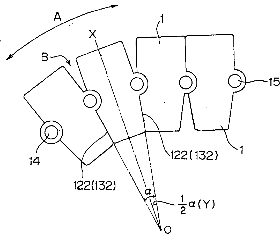
[0029] Referring now to the diagram, and in particular to figure 1 , shows in a perspective view the inner connection part 1 of the cable pulling chain according to the first embodiment of the invention. The inner connecting member 1 is composed of a hollow rectangular ring member 11 which is molded from synthetic resin. The hollow annular inner connector 1 (11) has a pair of connecting pins 14 formed at its front end 12 (at the figure 1 In the center of the left side), a pair of diametrically opposite pinholes 15 are formed in a diametrically opposite relationship at its rear end 13 (in figure 1 center of left). The connecting pin 14 and the connecting hole 15 of the inner connecting piece 1 are respectively rotatably engaged with the pin hole 15 and the connecting pin 14 of the two inner connecting pieces 1, wherein the fitt...


PUM


Abstract

A cable drag chain includes a plurality of ring-like inner links pined together at front and rear ends thereof. Each of the inner links has opposite end faces serving as stopper surfaces engageable with the stopper surfaces of the adjacent inner links to limit the angle of pivotal movement between the adjacent inner links. A ring-like outer link is detachably mounted to a joint portion between two adjacent inner links and surround the joint portion so as to close a space formed between the two adjacent inner links.

Description

technical field [0001] The invention relates to a cable chain for supporting and guiding flexible components such as cables and hydraulic or pneumatic hoses, which are connected between fixed and moving parts of machine tools, earth-moving machines, conveyors and the like. Background technique [0002] Cable drag chains have been invented to support and guide flexible components such as electrical cables and hydraulic or pneumatic tubes while protecting them from damage or entanglement due Subjected to twisting or stretching, resulting in entanglement, where the flexible member is attached to a machine tool, earthmoving machine or conveyor as described above. [0003] An example of such a conventional cable drag chain is disclosed in Japanese Patent Specification No. SHO-62-15008, entitled "Energy Delivery Catheter Stent". The inventive catheter holder includes inner tube parts made of synthetic resin, and outer tube parts made of metal, wherein the outer tube parts are arr...

Claims


Application Information

Patent Timeline
Patent Type & Authority Applications(China)
IPC IPC(8): F16G13/07F16G13/02F16G13/16H02G1/00H02G11/00
CPCH02G11/006F16G13/16H02G1/00
Inventor 小官庄一郎松田孝之水元三千代
Owner TSUBAKIMOTO CHAIN CO
Why Eureka
Try Eureka