Transmitter and tributary interface board

A technology of a transmission device and a branch circuit is applied in the field of branch circuit interface substrates, which can solve the problems of needing funds and being unable to respond flexibly to communication needs.

Inactive Publication Date: 2002-04-10
KK TOSHIBA
View PDF0 Cites 1 Cited by
  • Summary
  • Abstract
  • Description
  • Claims
  • Application Information

AI Technical Summary

Problems solved by technology

However, there is a problem that this special design and development requires funds and ca

Method used


Image

  • Transmitter and tributary interface board
  • Transmitter and tributary interface board
  • Transmitter and tributary interface board

Examples


Embodiment Construction

[0035] Hereinafter, we describe in detail embodiments of the present invention with reference to the drawings.

[0036] (first embodiment)

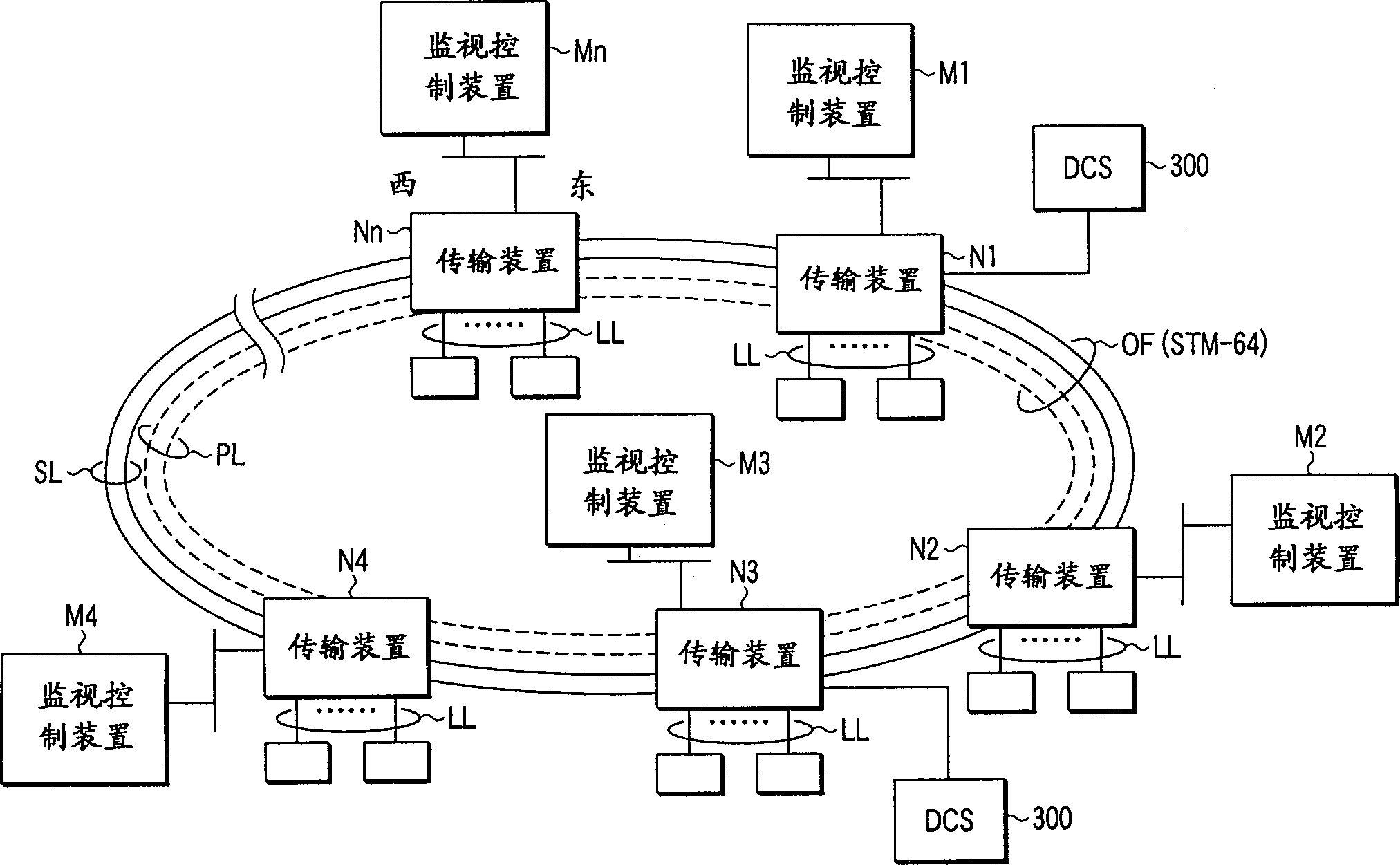
[0037] figure 1 It is a system configuration diagram showing the transmission system according to the embodiment of the present invention. This system includes n transmission devices N1 to Nn connected in a chain by line cables OF. The transmission capacity of the line cable OF is the so-called STM-64 (Synchronous Transport Module-Class 64) in SDH.

[0038] The line cable OF has an active system transmission line SL and a backup system transmission line PL, and each transmission line SL, PL has a clockwise (CW) line and a counterclockwise (CCW) line.

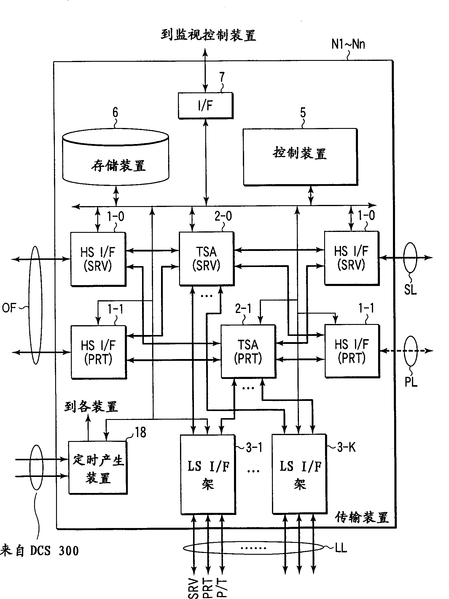
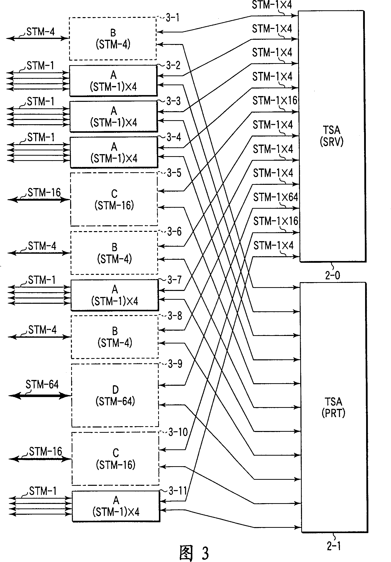
[0039] The transmission devices N1 to Nn drop predetermined time slots from the time slots for time-division multiplexing the STM-64 signal transmitted through the line cable OF. This tagged time slot is sent as a lower-order group signal to a lower-order group de...


PUM


Abstract

Multiplexing/de-multiplexing sections (14, 15, 19) are respectively provided on STM-4 substrates (B1, B2), STM-16 substrates (C1 to C3), STM-64 substrates (D1 to D3) to de-multiplex each of an STM-4 signal, STM-16 signal, STM-64 signal from a tributary transmission line (LL) into STM-1 signals. Then, transmission interfaces extending from the respective above substrates to time slot exchanging sections (2-0, 2-1) are all uniformed to STM-1 which is a basic transmission speed in SDH.

Description

technical field [0001] The present invention mainly relates to a transmission device for transmitting data in a transmission system such as a submarine optical cable system and a tributary interface substrate provided in the transmission device, and particularly relates to a transmission system such as SDH (Synchronous Digital Hierarchy) / SONET (Synchronous Digital Hierarchy) A transmission device used in a network that specifies a basic transmission speed such as an optical fiber network, and a branch interface board of such a transmission device. Background technique [0002] SDH / SONET is a standard that determines a method for multiplexing digital signals. In SDH, a transmission speed of 156 Mbps (155.52 Mbps) called STM-1 (Synchronous Transport Module-Level 1) is used as a basic unit, and a speed N times this speed is defined as [STM-N]. In SONET, a transmission speed of 52 Mbps (51.84 Mbps) called OC-1 (Optical Carrier 1) is used as a basic unit...

Claims


Application Information

Patent Timeline
IPC IPC(8): H04J3/16
CPCH04J3/1611
Inventor 岩堀仁大谷满北岛基孝
Owner KK TOSHIBA
Why Eureka
Try Eureka