Rear wheel suspension device of cycle

A suspension device and rear wheel technology, applied in axle suspension devices, suspensions, elastic suspensions, etc., can solve the problems of restricting the freedom of weight distribution, difficulty in reducing the weight of the car body, and increasing manufacturing costs, so as to improve design freedom The effect of reducing weight, reducing manufacturing cost

Inactive Publication Date: 2002-04-17
HONDA MOTOR CO LTD
View PDF1 Cites 12 Cited by
  • Summary
  • Abstract
  • Description
  • Claims
  • Application Information

AI Technical Summary

Problems solved by technology

[0005] The above-mentioned technology controls the rear wheel to turn to the same direction as the turning direction (the turning direction of the front wheel) by the centrifugal force acting on the weight of the battery support frame 9 on which the battery 10 is mounted. The rear part of the car body, so it is difficult to reduce the weight of the car body, in addition, it also limits the degree of freedom in weight distribution
[0006] In addition, connecting parts such as control rods 74R, 74L and ball hinges installed at the ends of these control rods 74R, 74L are required, the number of parts increases, and the manufacturing cost is increased.

Method used


Image

  • Rear wheel suspension device of cycle
  • Rear wheel suspension device of cycle
  • Rear wheel suspension device of cycle

Examples


Embodiment Construction

[0025] Embodiments of the present invention will be described below with reference to the accompanying drawings. Also, assume that the diagram is viewed in the direction of the symbol.

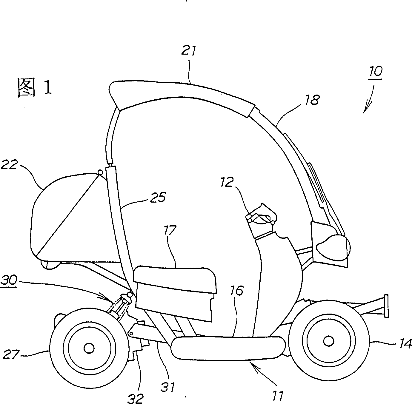
[0026] Fig. 1 is the side view of the vehicle equipped with the rear wheel suspension device of the present invention, as the four-wheeled vehicle 10 of vehicle, in the front part of vehicle body 11, a pair of left and right pairs of control steering with handlebar 12 that can rotate freely are installed. The rear wheel suspension device 30 of the present invention is attached to the rear portion of the vehicle body 11 to the front wheels 13 and 14 (inner symbol 13 is not shown). In addition, 16 is a floor for placing the driver's feet, 17 is a vehicle seat, 18 is a windshield, 21 is a shed, and 22 is a trunk.

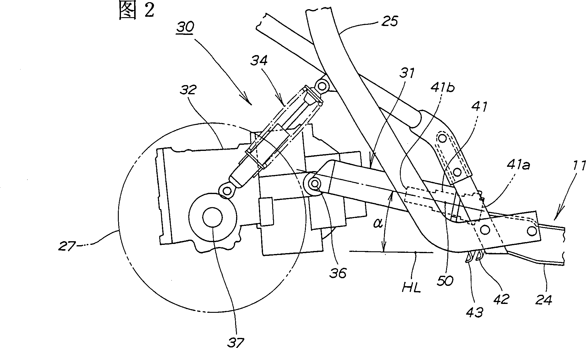
[0027] Fig. 2 is the side view of rear wheel suspension device of the present invention, and rear wheel suspension device 30 is made up of following parts: be installed in the connect...


PUM


Abstract

In a rear wheel suspension system (30) in a four-wheeled vehicle (10) wherein a joint member (31) is mounted in a rear portion of a vehicle body (11) with a pair of left and right front wheels (13,14) secured thereto, the joint member (31) comprising a roll shaft (41) extending substantially in the longitudinal direction of the vehicle body and a vertical swing shaft (36) extending in the transverse direction of the vehicle body, and a power unit (32) which supports rear wheels (26) and (27) is connected to a rear part of the joint member (31), thereby allowing the power unit (32) to be secured to the vehicle body (11) rollably and swingably, the roll shaft (41) is mounted so that a front end part (41a) thereof is positioned lower than a rear end part (41b) thereof. It is possible to easily attain the reduction in weight of the vehicle, set a weight distribution of the vehicle freely, and improve the vehicular design freedom.

Description

technical field [0001] The present invention relates to a rear wheel suspension device for a vehicle which is convenient for reducing the weight of the vehicle, is suitable for increasing the degree of freedom in design, and has a simple structure. Background technique [0002] As everyone knows, for example, the device described in Japanese Patent Publication No. 5-39073 "Swing Type Vehicle" is a device that uses a rotating shaft extending along the front and rear directions of the car body to rotatably install the rear wheel axle on the rear of the car body, and simultaneously pass The swing shaft extending along the left and right direction of the car body enables it to swing up and down, and the rear wheel suspension device of the vehicle is installed on the rear wheel axle. [0003] in the above-mentioned bulletin Figure 10 The swing type vehicles described in (A) to (C) are: at the front portion of the vehicle frame 1, there is a pair of left and right front wheels Wf...

Claims


Application Information

Patent Timeline
Patent Type & Authority Applications(China)
IPC IPC(8): B60G9/02B62K5/00B62K5/01B62K5/05B62K5/08B62K25/04B62K25/20
CPCB62K25/20B62K5/01B62K5/10
Inventor 大关孝高柳真二小林裕悦古田慎司田上卓也高本浩
Owner HONDA MOTOR CO LTD
Why Eureka
Try Eureka