Descaling device for steam generator

A steam generator and scaling technology, applied in steam generation, components of steam boilers, steam boilers, etc., can solve problems such as expanding the cleaning range and difficult to clean nozzles

Inactive Publication Date: 2002-04-17
MITSUBISHI HEAVY IND LTD
View PDF1 Cites 20 Cited by
  • Summary
  • Abstract
  • Description
  • Claims
  • Application Information

AI Technical Summary

Problems solved by technology

[0022] (3) The effective cleaning diameter of the water jet in the air is small, so it is difficult to expand the cleaning range with the cleaning nozzle incorporated in the spray gun

Method used


Image

  • Descaling device for steam generator
  • Descaling device for steam generator
  • Descaling device for steam generator

Examples


Embodiment Construction

[0045] Hereinafter, preferred embodiments of the present invention will be described with reference to the accompanying drawings. In the drawings, elements that are the same as or corresponding to those in the above examples are identified by the same reference numerals. In addition, as can be seen from the following description, the present invention is not limited to this embodiment, but various improvements are possible.

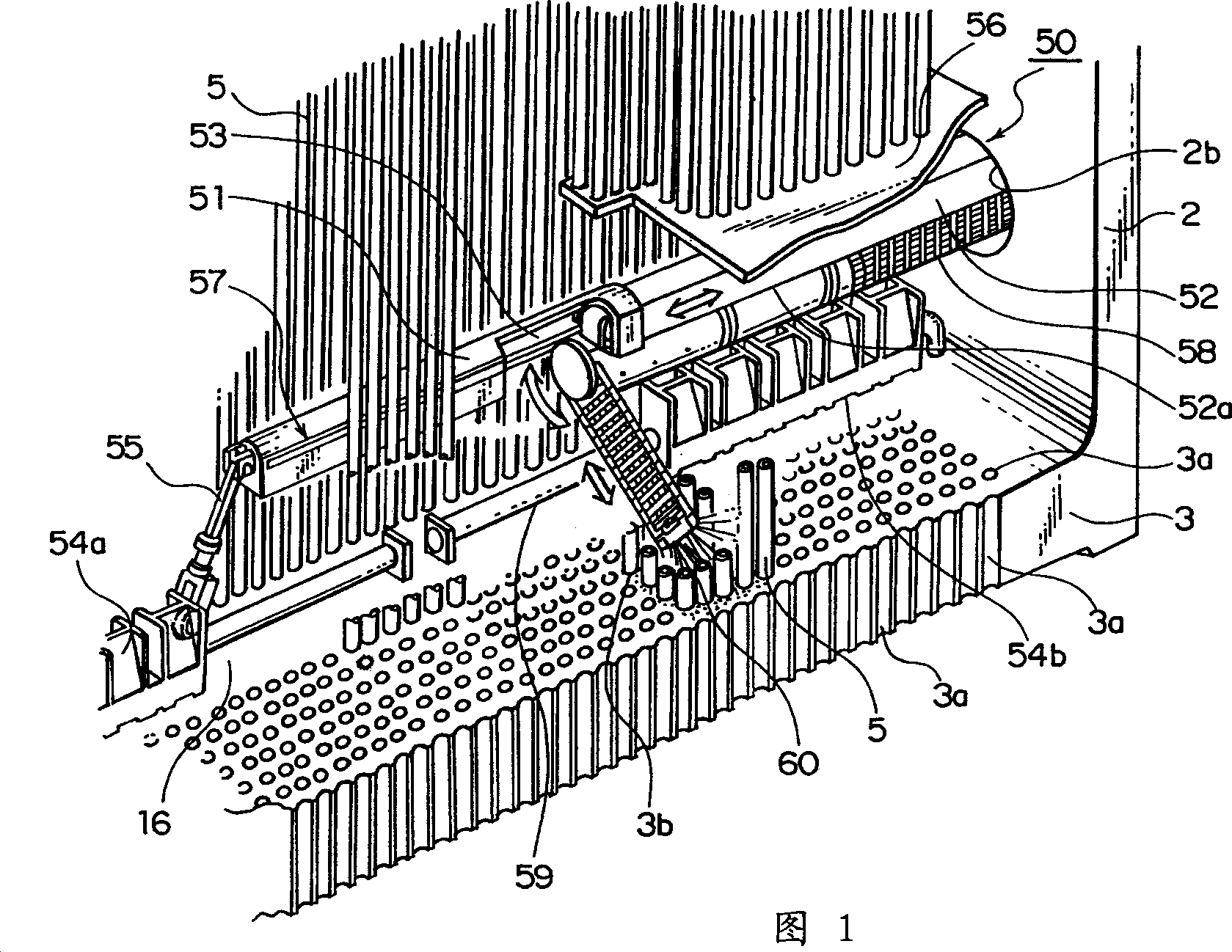
[0046] In FIG. 1, the main body part 2 shown is a scale removal device 50 for cleaning the part centered on the tube sheet according to the present invention. The tube sheet 3 has a large number of holes 3a, and the ends of the heat conducting tubes 5 are inserted into the holes and fixed in the holes in a water-tight manner. In addition, in the main body part 2, a pair of diametrically opposed circular exploration holes or observation holes 2b (only one of them is shown) is formed relatively close to the upper surface of the tube sheet 3, and the scale remov...


PUM


Abstract

A descaling device used to remove scales deposited on the inside of a shell and tube heat exchanger type steam generator, comprising a flexible lance which holds high-pressure water hose and is movable relative to tube plates, tube supporting plates, and heat-transfer pipes and a washing head installed at the tip of the flexible lance, wherein cavitation generating two nozzle holes communicating with the high-pressure water hoses are formed inside the washing head, whereby air bubbles are produced at the time of washing and an impact pressure produced when these bubbles burst is propagated so as to eliminate scales over a wide range.

Description

Technical field [0001] The present invention relates to a device for removing residue or scale, for example, on the tube sheet and in the tube bundle of a heat exchanger, such as a steam generator used in a nuclear power plant or the like. Background technique [0002] In order to understand the present invention, it is necessary to describe a steam generator used in a nuclear power plant or the like. Therefore, refer to Picture 10 A brief description of the steam generator. [0003] in Picture 10 Here, reference numeral 1 identifies the steam generating part of the steam generator. The steam generating part 1 has a substantially cylindrical body part 2 in which each hand hole or observation hole (only one of them is identified by the reference numeral 17) is symmetrically opposed to each other. In the lower part of the main body part 2, a tube plate 3 is arranged, which defines the water chamber 4 together with the bottom 2a of the main body part 2. On this tube plate 3, a lar...

Claims


Application Information

Patent Timeline
Patent Type & Authority Applications(China)
IPC IPC(8): B08B3/02B08B3/10C02F1/00F22B37/47F22B37/48F28G1/16F28G9/00F28G13/00F28G15/04
CPCF22B37/475B08B3/102F28G1/166F28G13/00F22B37/483F28G9/00
Inventor 白石直市冈丈彦衣笠利行冈田英也中尾文俊
Owner MITSUBISHI HEAVY IND LTD
Why Eureka
Try Eureka