Device for compressing objects and a high-pressure press

A technology of objects and indenters, applied in the field of high-pressure hydraulic presses, can solve problems such as inability to eliminate damage

Inactive Publication Date: 2002-05-08
费罗马托姆ANP有限责任公司
View PDF1 Cites 9 Cited by
  • Summary
  • Abstract
  • Description
  • Claims
  • Application Information

AI Technical Summary

Problems solved by technology

Although this structure is more expensive, it does not eliminate damage caused by forces acting in the circumferential direction

Method used


Image

  • Device for compressing objects and a high-pressure press
  • Device for compressing objects and a high-pressure press
  • Device for compressing objects and a high-pressure press

Examples


Embodiment Construction

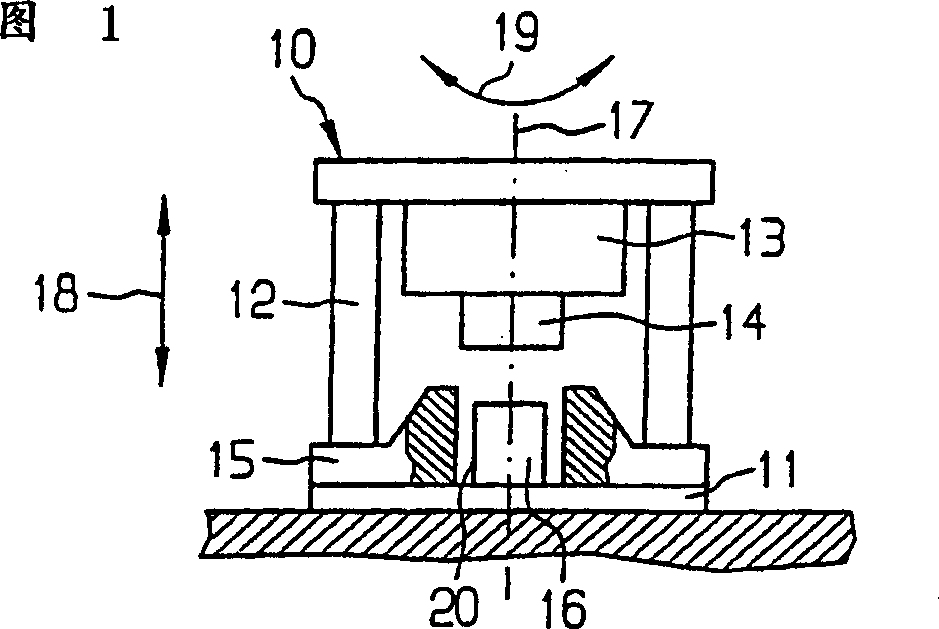
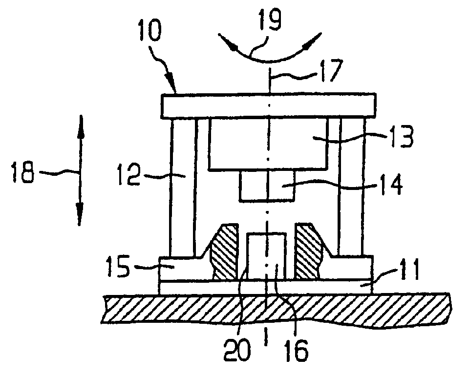
[0024] The device 10 according to the present invention shown in FIG. 1 includes: a base plate 11 , a frame 12 , a slider 13 and a press 14 . A jig 15 is also provided, and a barrel 16 is inserted into the inner space of the jig 15 . The ram 14 is guided so as to be movable in the direction indicated by the arrow 18 relative to the frame. Appropriate devices (not shown in detail in the figure) are mounted on the slider 13 for pushing the pressure head 14 to move. When the barrel 16 is compressed, the bulky object contained in the barrel 16 exerts a force on the ram 14 in the circumferential direction. This is important because the compressive force on the object being compressed (for example, a bucket containing such an object) is applied non-concentrically by the bulky object.

[0025] In high-pressure presses, especially high-pressure hydraulic presses, a compressive force of the magnitude of several thousand tons—mainly of the order of 2000 tons—is generally exerted on th...


PUM


Abstract

The invention relates to a device for compressing objects (16) that comprises a base plate (11), a frame (12) and a stamp head (14) which is displaceably guided on the frame (12). When compressing bulky objects (16), forces can arise in the peripheral direction of the stamp head (14). In order to reduce the forces introduced into the frame (12), the stamp head (14) is designed such that it can rotate with regard to the frame (12).

Description

technical field [0001] The present invention relates to a device for compressing objects, and more particularly to a high-pressure hydraulic press for compressing objects, comprising a base plate, a frame and a ram guided to move on the frame. Background technique [0002] Such devices have different structures and are suitable for compressing different forms of objects. For example, devices are known which are lighter in construction and require strictly limited and smaller compressive forces. These devices are mainly designed as screw compression devices (GB 1513367). Apparatus suitable for compressing twisted cylinders filled with waste, however, must meet stringent design criteria in terms of compressive force and structure. In particular, such waste may also be radioactively or otherwise contaminated waste enclosed in drums or other suitable containers. [0003] During the compression work of the press, the force acting in the circumferential ...

Claims


Application Information

Patent Timeline
Patent Type & Authority Applications(China)
IPC IPC(8): G21F9/30B30B9/30B30B9/32B30B15/06G21F9/28G21F9/36
CPCB30B15/065G21F9/28
Inventor 克劳斯·布林曼弗雷德·克拉珀维克托·格利亚
Owner 费罗马托姆ANP有限责任公司
Why Eureka
Try Eureka