Conveyor system switch using tubular linear induction motor

A technology of linear induction and electric motor, applied in the direction of propulsion system, electric components, conveyor objects, etc., can solve the problems of complex pipeline supply system and compressor, high maintenance cost, etc.

Inactive Publication Date: 2002-05-15
JERVIS B WEBB INT CO
View PDF1 Cites 9 Cited by
  • Summary
  • Abstract
  • Description
  • Claims
  • Application Information

AI Technical Summary

Problems solved by technology

One problem with this system is the complexity of the piping, supply systems and compressors require

Method used


Image

  • Conveyor system switch using tubular linear induction motor
  • Conveyor system switch using tubular linear induction motor
  • Conveyor system switch using tubular linear induction motor

Examples


Embodiment Construction

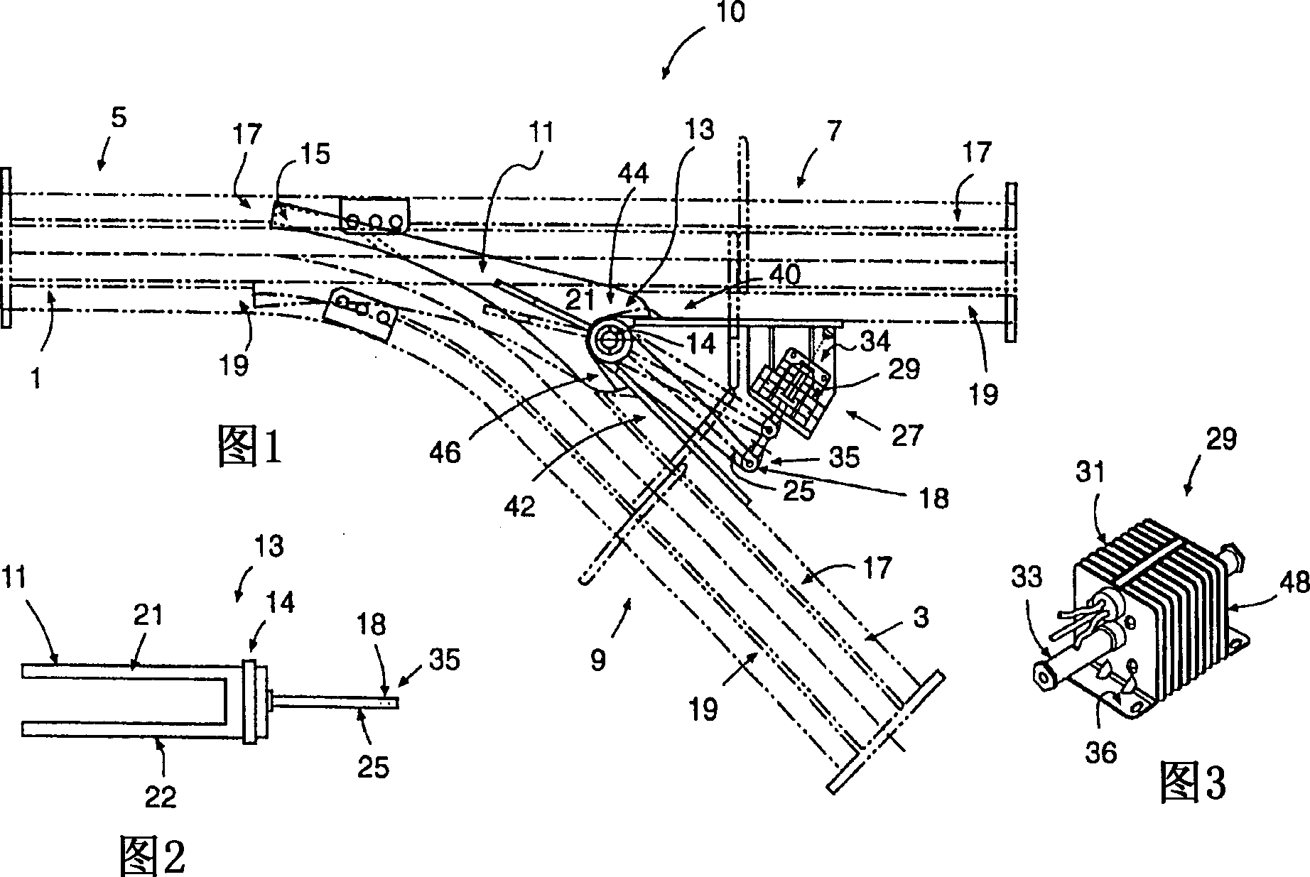
[0027] In FIG. 1, one embodiment of the present invention is a switch assembly 10 for use in a system switchable between powered and non-powered drives. Typically, these systems include powered and non-powered tracks. The chain moves along the power-driven track, and the trolley that supports the conveying object, such as a car body slide or a car body carrier, moves along a non-power-driven track. The chain is driven by the driving device, and the chain drives the trolley through the chain buckle. Powered and non-powered conveying systems are well known in the art and, therefore, will not be described in detail here. Although the turnout apparatus of the present invention has been described as an example for use in a system switchable between powered and non-powered drives, it will be understood that the invention is not limited to use with such systems. Elevated powered and non-powered systems, and other conveyor systems where conveyor components move along a track or the ...


PUM


Abstract

A conveyor switch for a conveyor track comprising a tubular linear induction motor as the switch drive. A switch tongue is adapted to be pivoted between first and second positions on the conveyor track and has a driving arm extending from one end thereof. The switch drive is operatively connected to the driving arm for driving the switch tongue, wherein the switch tongue is adapted to direct a moving conveyor component between first and second paths of travel on the conveyor track. Various means are provided to account for the linear movement of the switch drive in relation to the arcuate movement of the switch tongue. The switch assembly is especially adapted for switches in power and free conveyor systems.

Description

technical field [0001] The present invention relates to a switch of a conveying device for controlling the movement of the conveying device between two paths of motion, in particular, the present invention relates to a switch using a tubular linear induction motor which can drive the switch mechanism. Background technique [0002] Conveyor systems, such as powered and non-powered systems, typically have multiple interconnected tracks in which a switch plate movable between a first and second position is used to direct conveyed items from one track to another track. A switch plate generally consists of a rotating switch element having upper and lower tongue rails at one end and a drive arm at the other end, wherein the upper and lower tongue rails abut against the upper and lower rail flanges so that the The object goes to the appropriate track. In this manner, the switch plate is movable between a first and a second position to convey articles from one path to another like...

Claims


Application Information

Patent Timeline
IPC IPC(8): B65G47/64B61L23/00E01B25/26H02K33/00H02K41/025
CPCE01B25/26B61L23/005B61L5/06
Inventor 迪派克·戴维纳尼爱德华·E·波尔
Owner JERVIS B WEBB INT CO
Why Eureka
Try Eureka