Material taking device for sprayer assembly of flusher

A nozzle assembly and reclaiming device technology, applied in the direction of conveyor objects, transportation and packaging, conveyors, etc., can solve the problems of unable to adjust the output pressure, narrow range of upper and lower limits of output pressure, and difficulty in meeting the growth of production line production efficiency Market demand and other issues

Inactive Publication Date: 2022-04-01
岳阳职业技术学院
View PDF1 Cites 0 Cited by
  • Summary
  • Abstract
  • Description
  • Claims
  • Application Information

AI Technical Summary

Problems solved by technology

[0005] 1. Although the existing washer can easily disassemble the nozzle assembly to save space and be convenient to carry, the disassembled liquid outlets are prone to liquid leakage, and the hole diameter of the liquid outlet is fixed, so the pressure of the liquid outlet cannot be adjusted. The upper and lower limits of the outlet pressure are narrowed, which in turn affects the adaptability of flushing;
[0006] 2. The disassembled liquid outlet is exposed to the environment and is easily polluted, which increases the cleaning and sterilization workload of the washer;
[0007] 3. The pressing handle of the portable washer has no limit measures, which is prone to accidental touches and other problems
During the investigation and communication with the manufacturer, it was found that the production efficiency of the existing production line is difficult to meet the growing market demand, and some processes are still mainly operated manually, which restricts the improvement of production efficiency

Method used


Image

  • Material taking device for sprayer assembly of flusher
  • Material taking device for sprayer assembly of flusher
  • Material taking device for sprayer assembly of flusher

Examples


Embodiment Construction

[0040] The present invention is further illustrated by the following examples.

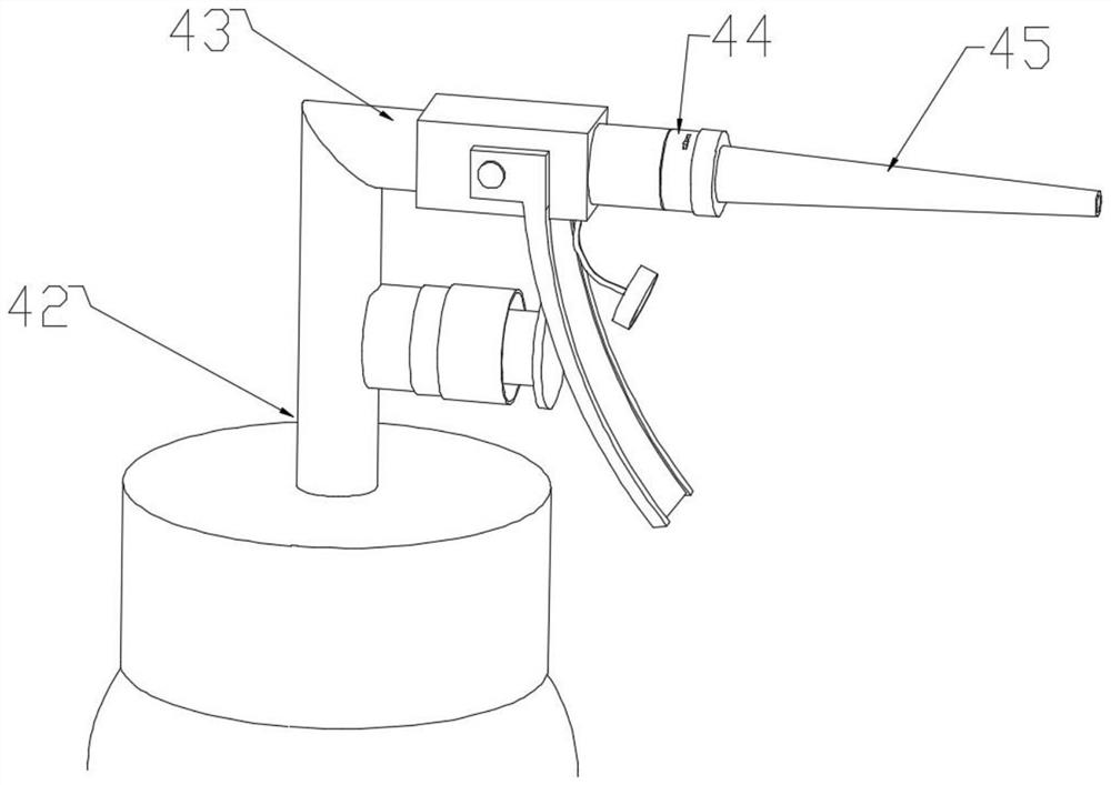
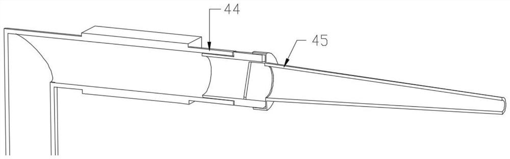
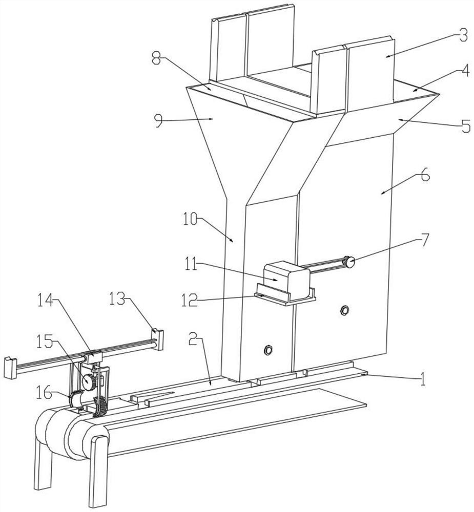
[0041] A material retrieving device for a nozzle assembly of a washer, comprising a conveyor belt 1, a nozzle unloading device, a connecting seat unloading device, and a tubular linear motor are sequentially arranged above the conveyor belt 1, and the mover 14 of the tubular linear motor is connected with a The clamping device is characterized in that the surface of the conveyor belt 1 is provided with a raised limit belt 2, and the surface array of the limit belt 2 is provided with a pair of nozzle limit grooves 18 and a connection seat limit groove 17, and the nozzle Both sides of the limiting groove 18 and the connecting seat limiting groove 17 are provided with notches 19; the nozzle blanking device includes a nozzle storage box 5, and the top of the nozzle storage box 5 is provided with a nozzle feeding port 4 and its The lower part is the nozzle blanking channel 6 with the bottom opening, an...


PUM


Abstract

The invention discloses a material taking device for a sprayer assembly of a flusher, and belongs to the technical field of flusher machining, the material taking device comprises a conveying belt, a nozzle blanking device, a connecting seat blanking device and a tubular linear motor are sequentially arranged above the conveying belt, a clamping device is connected to a rotor of the tubular linear motor, and a protruding limiting belt is arranged on the surface of the conveying belt. Paired nozzle limiting grooves and connecting seat limiting grooves are formed in the surface of the limiting belt in an array manner; the nozzle discharging device comprises a nozzle storage box, a nozzle feeding port is formed in the top of the nozzle storage box, the lower portion of the nozzle storage box is a nozzle discharging channel with an opening in the bottom end, and a first discharging conveying belt is arranged in the nozzle discharging channel. The connecting base discharging device comprises a connecting base storage box, a connecting base feeding port is formed in the top of the connecting base storage box, a connecting base discharging channel with an opening in the bottom end is formed in the lower portion of the connecting base storage box, and a second discharging conveying belt is arranged in the connecting base discharging channel. The clamping device comprises a driving gear, and a rotatable clamp is arranged below the driving gear.

Description

technical field [0001] The invention relates to the technical field of washer processing, in particular to a material retrieving device for a spray head assembly of a washer. Background technique [0002] Pressurize clean water or medicinal liquid and spray it into the oral cavity to remove food residues on the teeth or between the teeth. It is an effective technical means to protect the gums, reduce the reproduction of bacteria in the oral cavity, and prevent dental and oral diseases. Based on Devices of this technology are collectively referred to as oral irrigators. Clinically, for patients undergoing oral surgery and skin flap repair, oral irrigation should be used after surgery to remove oral secretions and attachments on the flap, prevent oral infection, and promote the healing of the patient's oral wound and the survival of the flap. There are many types of flushers to choose from on the market. [0003] Irrigators are usually divided into two types: desktop and han...

Claims


Application Information

Patent Timeline
Patent Type & Authority Applications(China)
IPC IPC(8): B65G47/90B65G47/14B65G15/58B65G17/12
CPCB65G47/902B65G47/14B65G15/58B65G17/12
Inventor 杨小抒骆雪曾雪芳夏振威刘勇
Owner 岳阳职业技术学院
Why Eureka
Try Eureka