A tubular linear motor mover

A linear motor and mover technology, applied in the field of motors, can solve the problems of high cost and complex structure of tubular linear motors, and achieve the effect of reasonable structure, small volume and reduced space

Active Publication Date: 2022-07-05
HANS LASER TECH IND GRP CO LTD +1
View PDF9 Cites 0 Cited by
  • Summary
  • Abstract
  • Description
  • Claims
  • Application Information

AI Technical Summary

Problems solved by technology

[0003] The existing tubular linear motor mover only provides a magnetic field for the motor, and the support between the motor mover and the motor stator needs to be completed by an additional linear guide rail, resulting in a complex structure and high cost of the tubular linear motor

Method used


Image

  • A tubular linear motor mover
  • A tubular linear motor mover
  • A tubular linear motor mover

Examples


Embodiment

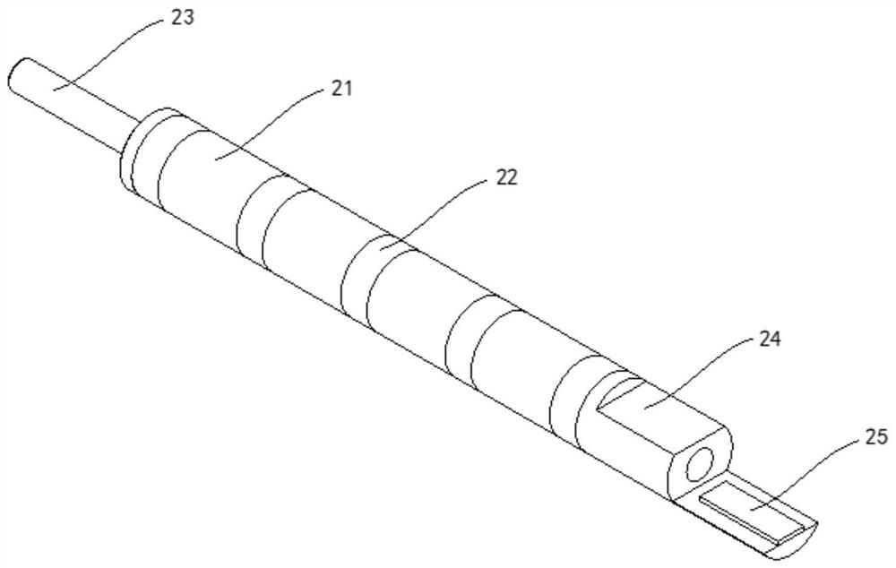
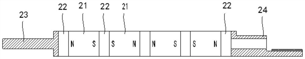
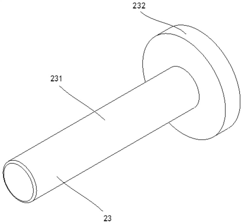
[0039] A tubular linear motor mover, such as Figure 1 to Figure 4 shown,

[0040] Including permanent magnet 21, iron core 22 and mandrel;

[0041] The iron cores 22 and the permanent magnets 21 are arranged alternately, so that the permanent magnets 21 are arranged between the iron cores 22 , the magnetic poles of the two adjacent permanent magnets 21 are opposite to each other, and the mandrels are arranged at the two ends of the magnets. The iron core 22 is away from the side of the permanent magnet, and the core shaft is slidably connected with the sliding sleeve 6 provided on the stator.

[0042] The tubular linear motor mover provided by the embodiment of the present invention can not only provide a magnetic field for the linear motor, but also can directly support the mover 2 on the sliding sleeve 6 of the stator through the mandrel to perform reciprocating linear motion without going through an intermediate conversion mechanism To directly generate linear motion, th...


PUM


Abstract

The embodiments of the present application belong to the technical field of electric motors, and relate to a tubular linear motor mover. The technical solution provided by this application includes permanent magnets, iron cores and mandrels; the iron cores and the permanent magnets are arranged in a staggered manner, so that the permanent magnets are arranged between the iron cores, and the magnetic poles of the two adjacent permanent magnets are opposite to each other. , the mandrel is arranged on the side of the iron core at both ends away from the permanent magnet, and the mandrel is slidably connected with the sliding sleeve arranged on the stator. The sliding structure between them does not need to occupy additional space, and the volume of the linear motor can be reduced, so that the linear motor can be applied to the occasions with stricter requirements on the volume of the motor. Therefore, the space occupied by the internal structure of the linear motor is better reduced, the internal structure of the motor is greatly optimized, the cost of the motor is reduced, and the manufacture and maintenance are easier.

Description

technical field [0001] The present application relates to the technical field of electric motors, and more specifically, to a tubular linear motor mover. Background technique [0002] A linear motor is a transmission device that directly converts electrical energy into linear motion mechanical energy without any intermediate conversion mechanism. It can be regarded as a rotating electrical machine which is cut radially and developed into a plane. The side derived from the stator is called the primary, and the side derived from the rotor is called the secondary. In practice, the primary and secondary are manufactured to different lengths to ensure that the coupling between the primary and secondary remains unchanged over the required travel range. Linear motors can be either short primary and long secondary, or long primary and short secondary. Considering the manufacturing cost and operating cost, take a linear induction motor as an example: when the primary winding is co...

Claims


Application Information

Patent Timeline
Patent Type & Authority Patents(China)
IPC IPC(8): H02K41/03
CPCH02K41/031
Inventor 肖文明何敏吴卫安王豫唐政高云峰
Owner HANS LASER TECH IND GRP CO LTD
Why Eureka
Try Eureka