Hinge mechanism of fixed belt

A technology of hinge mechanism and fixing parts, which is applied in the direction of connections, watch straps, mechanical equipment, etc., and can solve problems such as poor operability

Inactive Publication Date: 2002-06-12
SEIKO INSTR INC
View PDF0 Cites 14 Cited by
  • Summary
  • Abstract
  • Description
  • Claims
  • Application Information

AI Technical Summary

Problems solved by technology

[0004] However, according to the above-mentioned conventional buckle-type fixing belt, the 6 o'clock side strap and the 12 o'clock side strap are connected and locked together by a buckle to prevent it from falling off easily and can be firmly fixed on the arm. Therefore, this Poor operability to put on and take off
In addition, even in the case of using a bracelet-type fixing band as a watch band, there is a problem that the opening and closing operation is directly performed by the user's own hand, so the operability of putting on and taking off is the same. bad

Method used


Image

  • Hinge mechanism of fixed belt
  • Hinge mechanism of fixed belt
  • Hinge mechanism of fixed belt

Examples


Embodiment 1

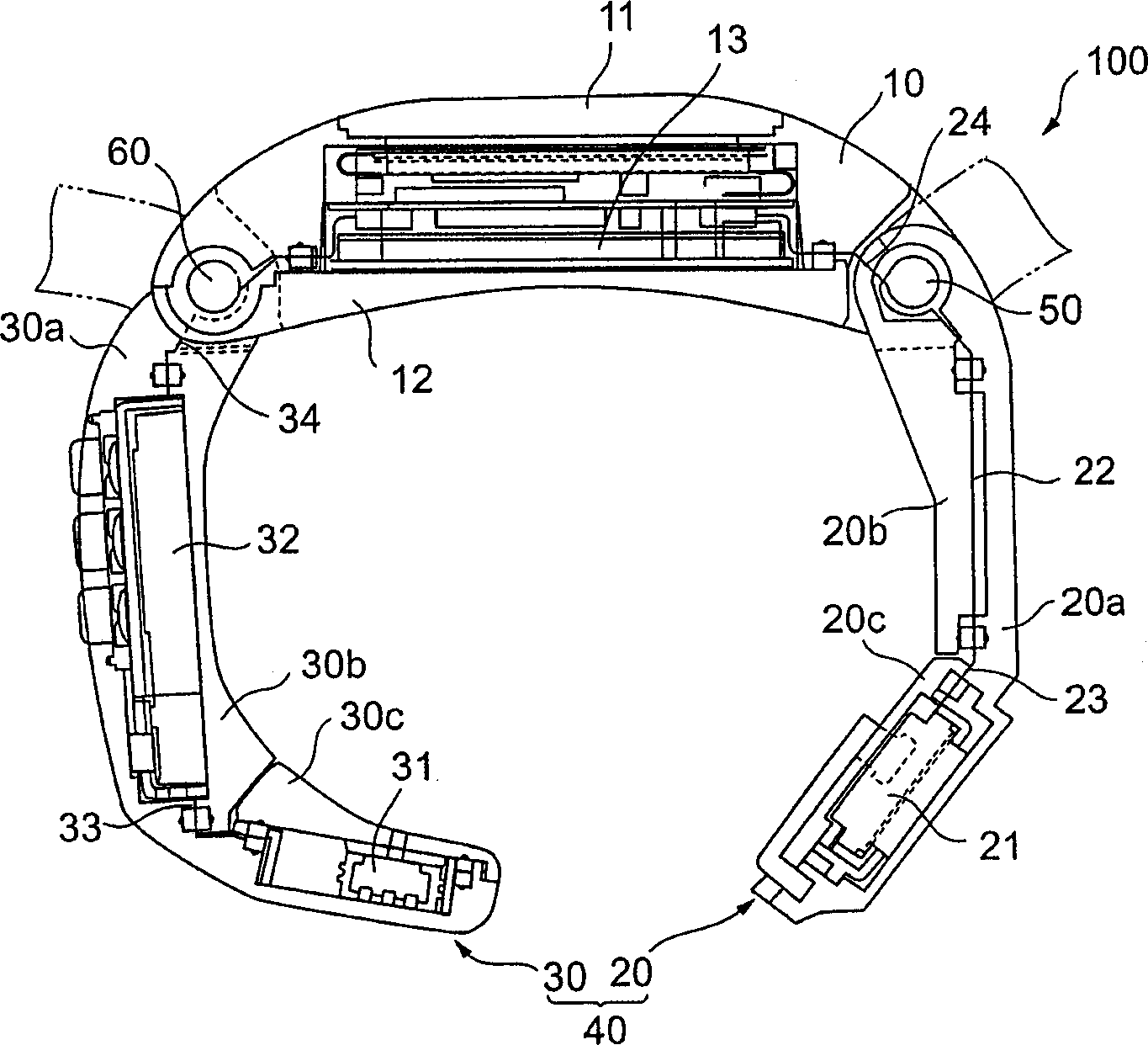
[0033] figure 1 is a cross-sectional view showing a wristwatch-type PHS communication terminal according to Embodiment 1 of the present invention. The watch-type PHS communication terminal 100 includes a case main body 10 and an endless fixing band 40 . The ring-shaped fixing band 40 includes an arcuate 12 o'clock side band 20 rotatably connected to the case body 10 at the 12 o'clock side of the case body 10 , and an arched 12 o'clock side band 20 rotatably connected to the case body 10 at the 6 o'clock side of the case body 10 . Side strap 30 at 6 o'clock.

[0034] The case main body 10 includes a PHS communication module 13 including electronic components such as an antenna, a battery, and a display panel for performing PHS communication in a space sealed by the glass plate 11 and the case bottom 12 . The glass plate 11 connected with the surface can protect the display panel, and the case bottom 12 is connected with the bottom surface. The arcuate 12 o'clock side band 20...

Embodiment 2

[0055] Figure 10 is a perspective view for explaining a watch-type PHS communication terminal according to Embodiment 2 of the present invention. Figure 11 is a partial sectional view of a wristwatch type PHS communication terminal according to Embodiment 2 of the present invention. Embodiment 2 adds to the structure of Embodiment 1 a button lever 71, strikers 72 and 74, and a sliding washer 73 shown below. That is, when the buttons 50 and 60 on the 12 o'clock side and the 6 o'clock side are connected by the button lever 71 and the strikers 72, 74, the bands 20 and 30 can be simultaneously opened by a one-touch operation.

[0056] Additionally, the sliding washers 73 and 75 hold the button stem 71 when the buttons 50 and 60 are rotated within the belt opening angle and assist in the rotation of the buttons 50 and 60 and the button stem 71 .

[0057] In addition, although the above-mentioned embodiment has been described by the example of the fixing strap on the PHS communi...


PUM


Abstract

To provide a mounting strap capable of being mounted in accordance with a size of an object to be mounted, easy to attach and detach and having high general purpose performance. According to a pipe hinge unit, when a button is pushed into a slide pipe until a fixed pin is butted to a portion intersected with an axial direction and a peripheral direction of a fixed pin slide hole, by urge force by a pipe return spring, the button is slid toward a side of a terminal end in the peripheral direction of the fixed pin slide hole, a rotational pipe is rotated relative to the button, thereby, a strap piece attached to the rotational pipe is rotated in an opening direction relative to a case main body attached to the slide pipe.

Description

technical field [0001] The invention relates to a hinge mechanism of a fixing belt. Background technique [0002] In general, as a fixing band for fixing a wristwatch or a mobile device, such as a wristwatch-type communication device or a wristwatch-type information device typified by a Personal Handyphone System (PHS) communication terminal, to an arm, there has been known a Two pieces of the 6 o'clock side strap and the 12 o'clock side strap connected at opposite ends of the housing body of the mobile device (hereinafter referred to as "6 o'clock side" and "12 o'clock side") are connected together and secured with a buckle. Lock it, and you can attach it to the strap on the arm. This type of belt is referred to herein as a buckle-type belt. Buckle-type belts are known that can be made of leather, or of fabric with a buckle, or of metal chains with connectors. [0003] In addition, in addition to this buckle type band, there is also a bracelet type band that can be forme...

Claims


Application Information

Patent Timeline
Patent Type & Authority Applications(China)
IPC IPC(8): A44C5/12A44C5/14G04B37/14
CPCA44C5/14G04B37/1486A44C5/12Y10T74/18568Y10T74/18304
Inventor 井口胜信伊东隆史
Owner SEIKO INSTR INC
Why Eureka
Try Eureka