Seat sliding device

A sliding device and seat technology, applied to vehicle seats, movable seats, chairs, etc., can solve the problems of increased number of parts, increased sliding operation force, and the inability of the upper guide rail 5 to slide smoothly.

Inactive Publication Date: 2002-06-19
JOHNSON CONTROLS AUTOMOTIVE SYSTEMS CORP
View PDF0 Cites 17 Cited by
  • Summary
  • Abstract
  • Description
  • Claims
  • Application Information

AI Technical Summary

Problems solved by technology

[0008] However, if the lower rail 2 of the conventional seat sliding device 1 has an elongated shape as described above, it is cumbersome to process the corresponding part due to dimensional error or the like, making it unfavorable to ease the size dispersion in the vehicle and reduce the corresponding parts of the seat.
like figure 2 As shown, when the rolling member 2 between the lower rail 2 and the upper rail 5 is tilted, the sliding operation force in

Method used


Image

  • Seat sliding device
  • Seat sliding device
  • Seat sliding device

Examples


no. 2 example

[0051] The second embodiment of the seat sliding device of the present invention will be described in detail below with reference to the accompanying drawings. In this case, the same reference numerals are used to denote the same components as in the first embodiment described above and detailed description thereof will be omitted.

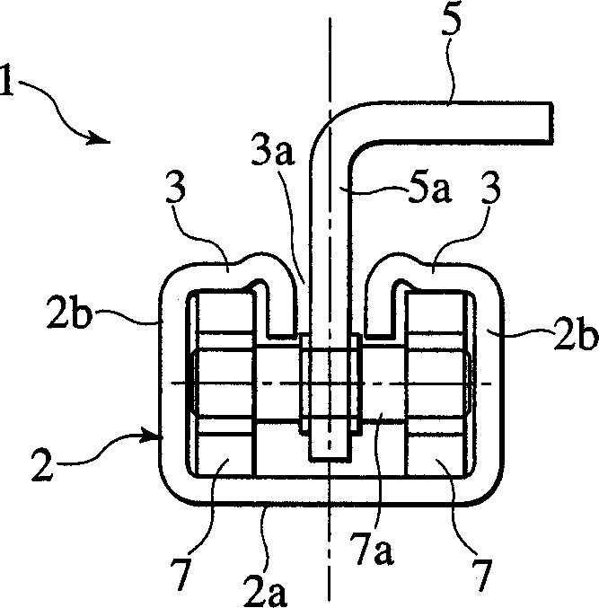
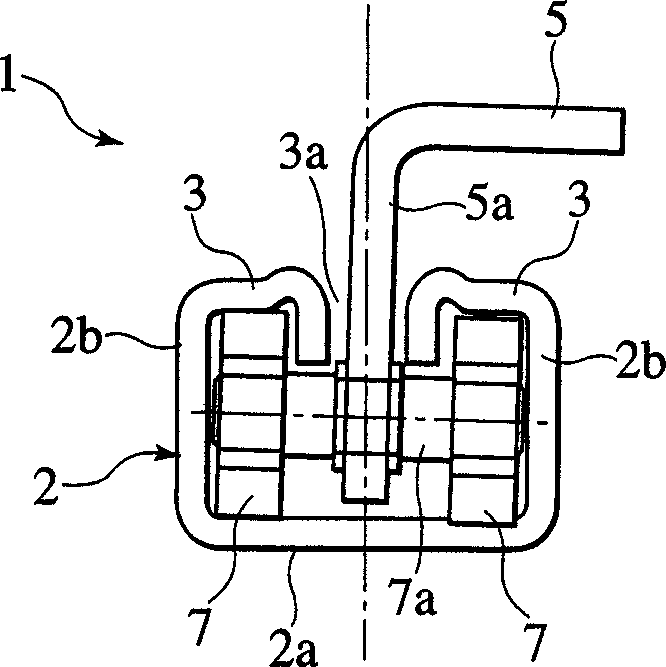
[0052] like Figure 7 As shown in and 8, the seat sliding device 1 of the second embodiment is mainly composed of a lower guide rail 12 and an upper guide rail 13 accommodated in the lower guide rail 12. The lower guide rail 12 is installed on the vehicle body floor surface along the longitudinal direction of the vehicle, and the upper guide rail 13 Sliding freely in the longitudinal direction of the vehicle, it is installed on the side of the seat body (not shown) and supports the seat body.

[0053] The lower guide rail 12 is constructed in such a way that a substantially upward C-shaped seat body 12a, a pair of left and right flanges 22 extend...

no. 3 example

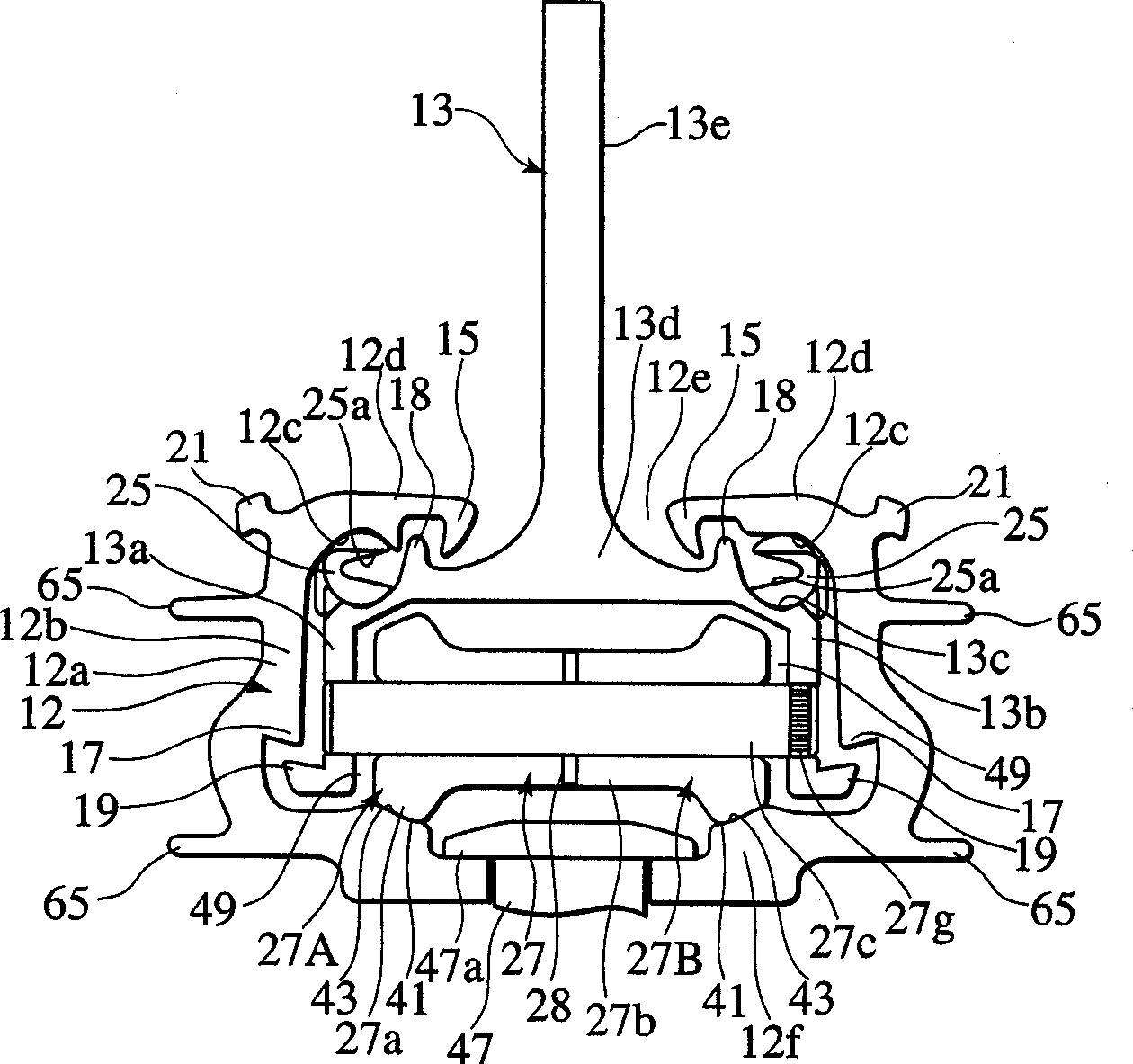
[0071] Figure 11 A third embodiment of the seat slide 11 is shown. The same reference numerals denote the same components as in the above-mentioned embodiments, and thus detailed description thereof will be omitted. According to this embodiment, the coil spring 42 for urging the pair of left and right rolling elements 27A and 27B is accommodated in the receiving groove portions 42a and 42b formed in the outer circumferential surfaces of the pair of left and right rolling elements 27A and 27B.

[0072] Therefore, it is possible to measure the gap between the pair of left and right rolling members 27A and 27B, but since there is an elastic force applied to the rolling members 27A and 27B due to the spring elasticity of the coil spring 42, it is possible to effectively eliminate the vehicle body mounting portion and the sliding member. Due to the contact surface between the rolling elements 27A and 27B and the rolling element receiving stepped portion 12f arranged as a concentr...


PUM


Abstract

Roller receiving step portions are formed in both sides of a bottom portion of a main body portion in a lower rail. A roller is inserted between the step portions in the lower rail and an upper wall in an upper rail. Left and right roller portions are formed so as to be separated into left and right sections in a substantially center portion of the roller. An elastic washer corresponding to an elastic body is inserted to a roller shaft at the separated position of the roller. Taper surfaces are formed in both side portions of the roller and are mounted on taper surfaces formed in the step portions in the lower rail and downward inclined toward a center in a width direction.

Description

technical field [0001] The present invention relates to a seat sliding device, and more particularly to a seat sliding device comprising a lower rail installed in a longitudinal direction for a floor surface of a vehicle and an upper rail which guides and supports the upper rail so as to slide freely in the longitudinal direction, And the upper guide rail is installed and fixed on the side of the seat main body. Background technique [0002] Generally, a seat of a vehicle has a seat body composed of a seat cushion, a seat back standing on the back for free rotation and adjustment, and the like, and the seat supports the cushion by a longitudinal sliding mechanism or constitutes a seat on the floor surface of the vehicle body. The analogue of the chair body thus has a structure that can be adjusted for free sliding in the longitudinal direction of the vehicle body and has a configuration that can make various changes to the seat arrangement in the passenger space. [0003] I...

Claims


Application Information

Patent Timeline
IPC IPC(8): B60N2/015B60N2/07
CPCB60N2/0725B60N2/071B60N2/01591B60N2/0715B60N2/075B60N2/07
Inventor 江口森幸藤本凉吉田知德
Owner JOHNSON CONTROLS AUTOMOTIVE SYSTEMS CORP
Why Eureka
Try Eureka