Fire-accident alarm system

A fire alarm system, fire technology, applied in the direction of fire alarms, alarms, instruments, etc., can solve problems such as low voltage levels

Inactive Publication Date: 2002-07-03
NOHMI BOSAI LTD
View PDF0 Cites 8 Cited by
  • Summary
  • Abstract
  • Description
  • Claims
  • Application Information

AI Technical Summary

Problems solved by technology

When transmitting the transmission signal transmitted through the signal line so that the voltage is repeated high and low, there is such a pr

Method used


Image

  • Fire-accident alarm system
  • Fire-accident alarm system
  • Fire-accident alarm system

Examples


Example Embodiment

[0035] Hereinafter, embodiments of the present invention will be described with reference to the drawings.

[0036] First, the outline of the present invention will be described.

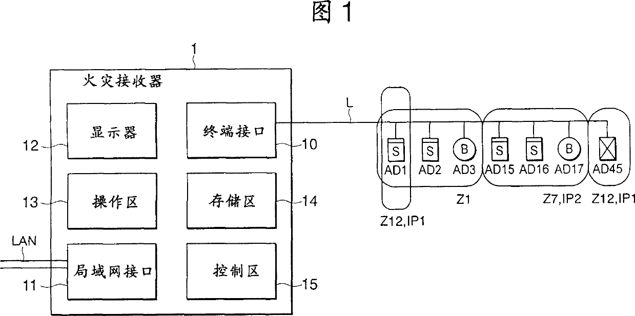
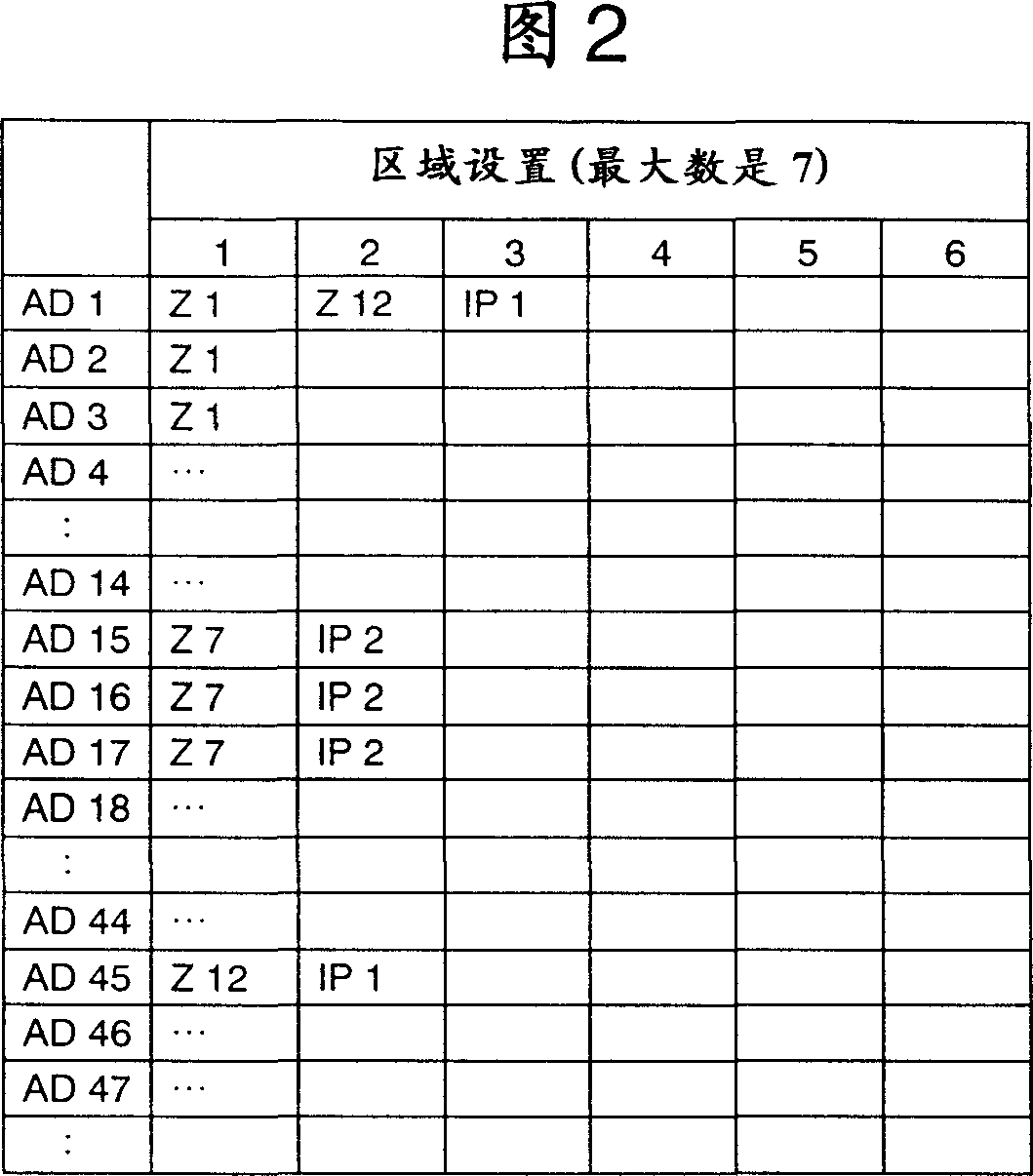
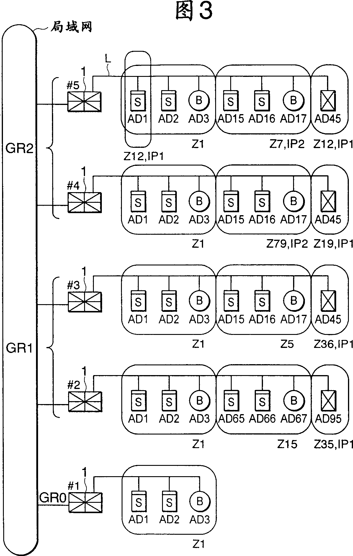
[0037] The present invention is a fire alarm system in which a plurality of fire receivers are connected and installed through a local area network (LAN), which monitor and control a plurality of end devices (fire sensors and controlled devices, such as area sound devices and smoke and dust prevention devices) and exhaust), in which fire receivers present on one and the same local area network are respectively given group numbers, and in which each fire receiver operates only in one and the same group to share information.

[0038] Also, a particular group can be set as a group number. Fire receivers authorized as a special group status, intercept any information from each fire receiver connected to the same local area network (LAN) regardless of group number.

[0039] So, even if a building becom...


PUM


Abstract

A fire alarm system provided with a fire receiver (1) to which a plurality of fire sensors and controlled apparatuses are connected. The fire receiver (1) comprises a LAN interface (11) for connecting with other fire receivers. When a fire sensor issues an alarm, the fire receiver transmits the fire information over the LAN together with a group number set in advance, and displays (12) only the fire information of the same group number when the fire receiver receives fire information transmitted from the other fire receivers via the LAN. Thus, even is a plurality of fire receivers are used in a large building divided into ridge sections, fire information can be shared without causing disorder.

Description

technical field [0001] The invention relates to a fire alarm system. Background technique [0002] Conventionally, in a fire alarm system composed of fire receivers connected to each other through a local area network, fire detection information of the fire receivers can be shared among each of the connected fire receivers through the local area network. [0003] Additionally, in conventional fire alarm systems, as multiple terminal devices connected to one fire receiver, controlled devices such as zone sound devices and smoke prevention and exhaust The sensors detect the fire and they are connected to the same fire receiver. The connection between them is done by the receiver unit. [0004] Also, a fire alarm system is configured such that a plurality of fire receivers are respectively connected by a local area network (LAN), and share data by exchanging data signals (hereinafter simply referred to as signals). In this case, there are two ways to transmit the signal. On...

Claims


Application Information

Patent Timeline
IPC IPC(8): G08B17/00G08B26/00
CPCG08B26/004G08B17/00
Inventor 山口靖夫崎原诚菱野浩一大木崇裕恩智宗大
Owner NOHMI BOSAI LTD
Why Eureka
Try Eureka