Unit comprising high-pressure discharging lamp and ignition antenna

A technology for high-pressure discharge lamps and antennas, applied in the field of high-pressure discharge lamps and ignition antennas, to achieve the effect of easy mass production

Inactive Publication Date: 2002-08-07
KONINKLIJKE PHILIPS ELECTRONICS NV
View PDF1 Cites 1 Cited by
  • Summary
  • Abstract
  • Description
  • Claims
  • Application Information

AI Technical Summary

Problems solved by technology

It has been found that, regardless of the presence or absence of the ignition antenna, a large degree of ignition delay occurs, which is a disadvantage

Method used


Image

  • Unit comprising high-pressure discharging lamp and ignition antenna
  • Unit comprising high-pressure discharging lamp and ignition antenna
  • Unit comprising high-pressure discharging lamp and ignition antenna

Examples


Embodiment Construction

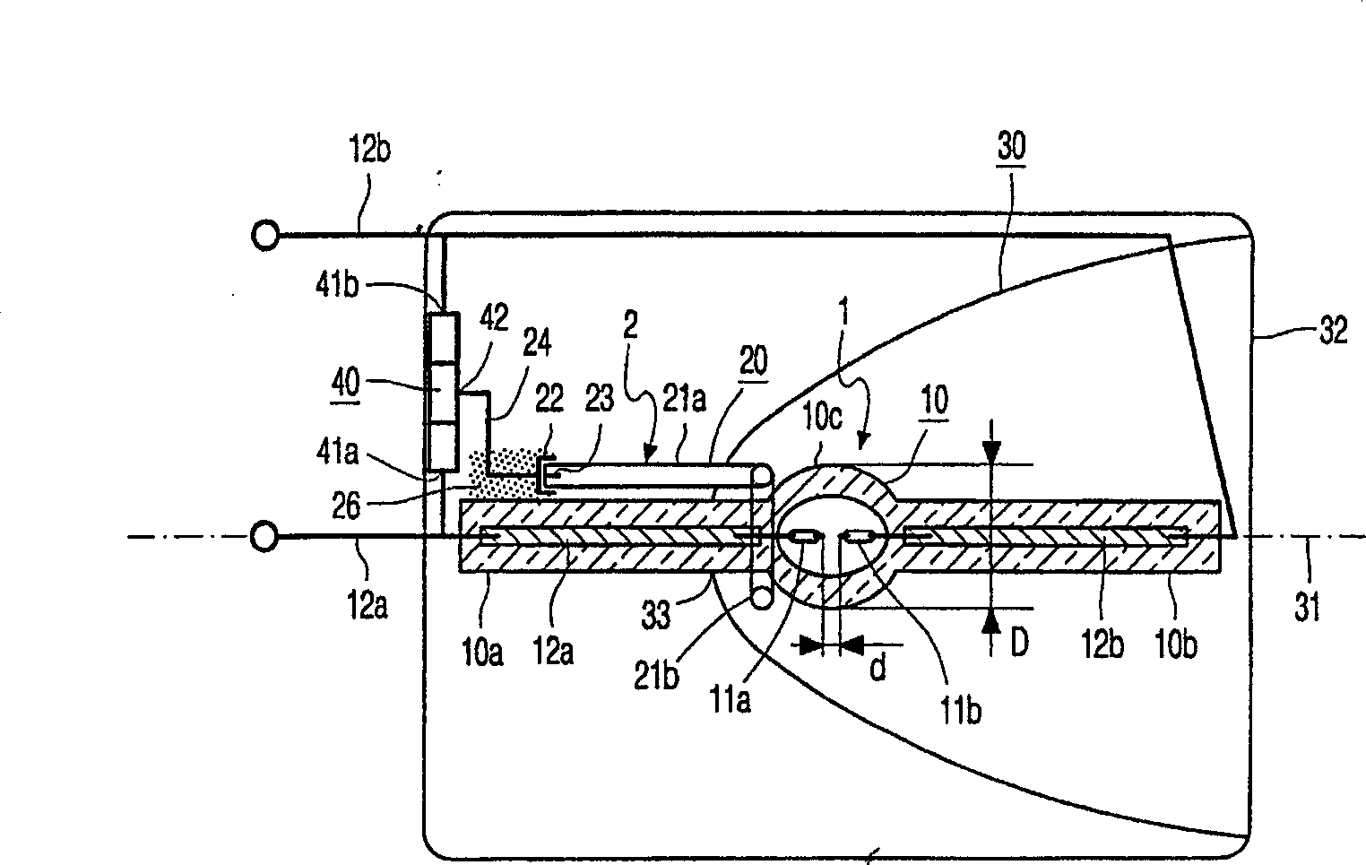
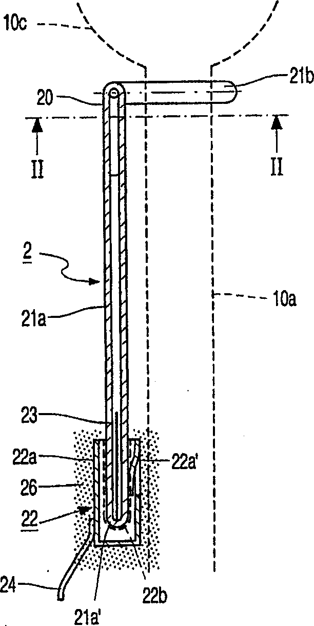
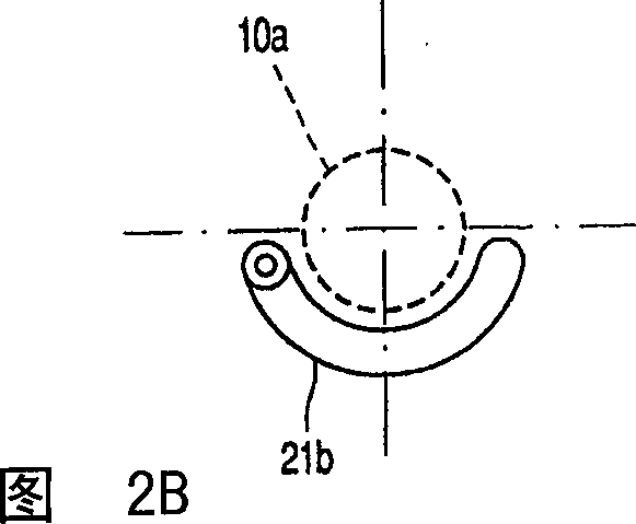
[0017] figure 1 A device comprising a high pressure discharge lamp 1 and an ignition antenna 2 is shown. The high-pressure discharge lamp is provided with a light-transmitting and airtight lamp housing 10, and the lamp housing 10 contains an ionizable filler. In this case, the filling contains one or more inert gases (here argon at a filling pressure of 100 mbar), at least 0.2 mg / mm 3 of mercury and eg 10 -6 -10 -4 μmol / mm 3 One or more halides of (Cl, Br, I halides), here in the form of mercury bromide. exist figure 1 In , the lamp housing is made of quartz glass, but it can also be made of ceramic materials. The first and second electrodes 11a, 11b are disposed in the lamp envelope 10, and the distance between the two electrodes is 1 mm. The maximum outer diameter D of the lamp housing 10 is 9 mm. The electrodes 11a, 11b are each connected to an own current conductor 12a, 12b, which conductors 12a, 12b each extend from the lamp vessel 10 to the outside. An ignition ...


PUM


Abstract

A short-arc discharge lamp (1) in accordance with the invention is provided with a light-transmitting, gastight lamp vessel (10), which is provided with an ionizable filling. A first electrode and a second electrode (11a, 11b), respectively, are arranged in the lamp vessel (10) and are each connected to a current conductor of their own (12a, 12b), respectively, which issues from the lamp vessel to the exterior. An ignition antenna (2) is arranged near the lamp vessel, which ignition antenna is connected to a further current conductor (24). The ignition antenna comprises an antenna vessel (20) and a further outer electrode (22), which antenna vessel (20) is closed in a gastight manner and provided with an ionizable filling, the further outer electrode (22) being connected to the further current conductor (24). According to the invention, the antenna encloses an electroconductive element. In this way, very small ignition delays are guaranteed, even if the lamp has been in a dark environment for some time.

Description

technical field [0001] The invention relates to a device comprising a high-pressure discharge lamp and an ignition antenna. The high-pressure discharge lamp is provided with a light-transmitting, airtight lamp envelope, the lamp envelope contains an ionizable filling, and first and second electrodes are arranged in the lamp envelope. Each electrode is connected to its own current conductor, which extends from the lamp envelope to the outside. The ignition antenna arranged near the lamp envelope is provided with an airtight antenna chamber, which has an ionizable filling. The ignition antenna is also provided with There is another external electrode, which is arranged on the outer surface of the antenna chamber and is connected to another current supply conductor. Background technique [0002] Such a device comprising a high pressure discharge lamp and an ignition antenna is disclosed in 99 / 48133. This known lamp has a relatively short discharge arc which enables the light p...

Claims


Application Information

Patent Timeline
Patent Type & Authority Applications(China)
IPC IPC(8): H01J61/54H01J61/86
CPCH01J61/547H01J61/54
Inventor H·C·M·范登纽温惠岑J·M·德雷格特
Owner KONINKLIJKE PHILIPS ELECTRONICS NV
Why Eureka
Try Eureka