Resistance furnace

A technology of resistance furnace and furnace chamber, which is applied in electric furnace heating, furnace cooling, etc., and can solve the problem of difficult temperature distribution adjustment due to temperature drop

Inactive Publication Date: 2008-02-27
HERAEUS QUARZGLAS
View PDF8 Cites 1 Cited by
  • Summary
  • Abstract
  • Description
  • Claims
  • Application Information

AI Technical Summary

Problems solved by technology

[0008] In high performance electric resistance furnaces (approximately 100kW and above), the temperature drop is especially pronounced and it is more difficult to regulate and maintain a uniform temperature distribution

Method used


Image

  • Resistance furnace
  • Resistance furnace
  • Resistance furnace

Examples


Embodiment Construction

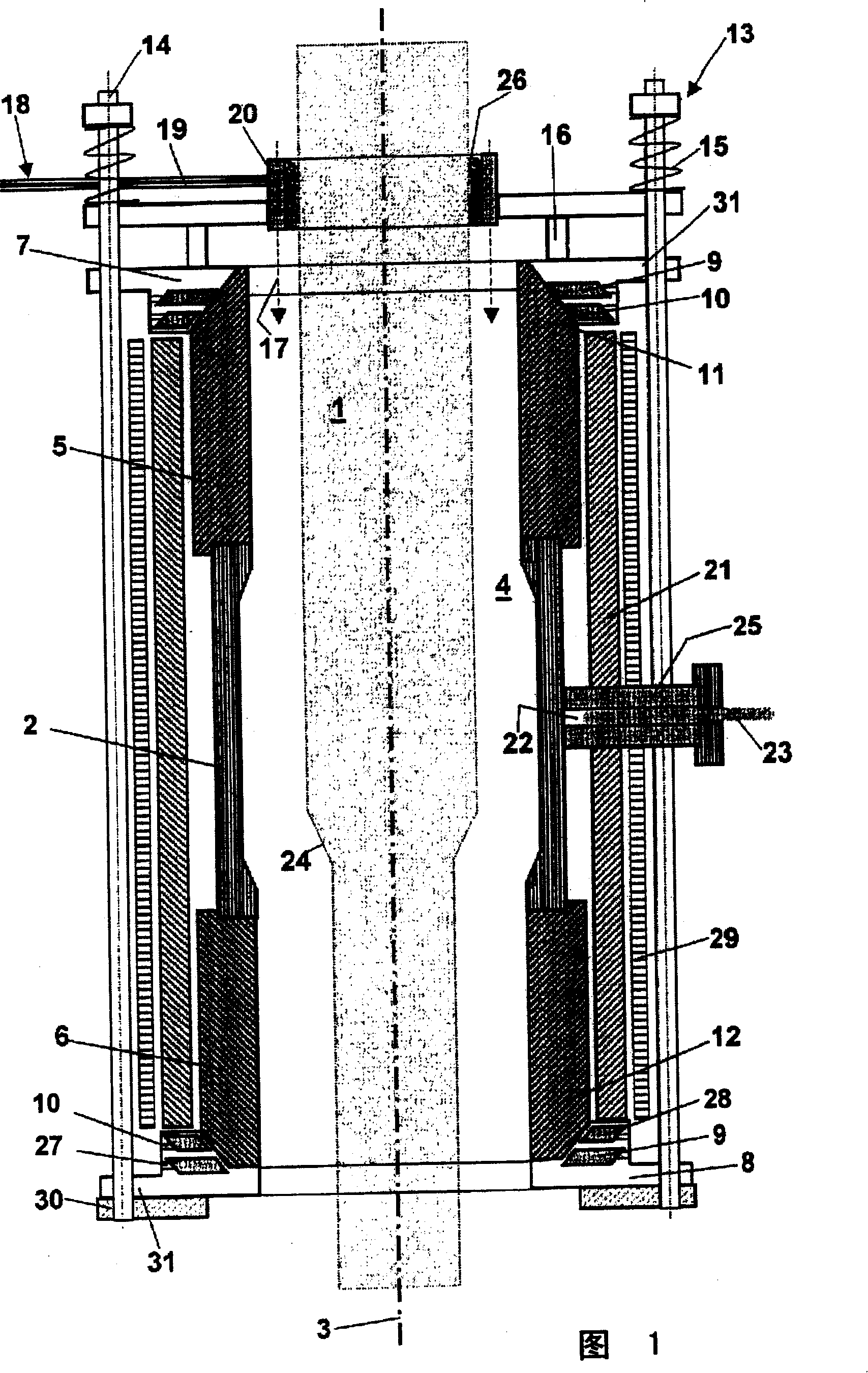
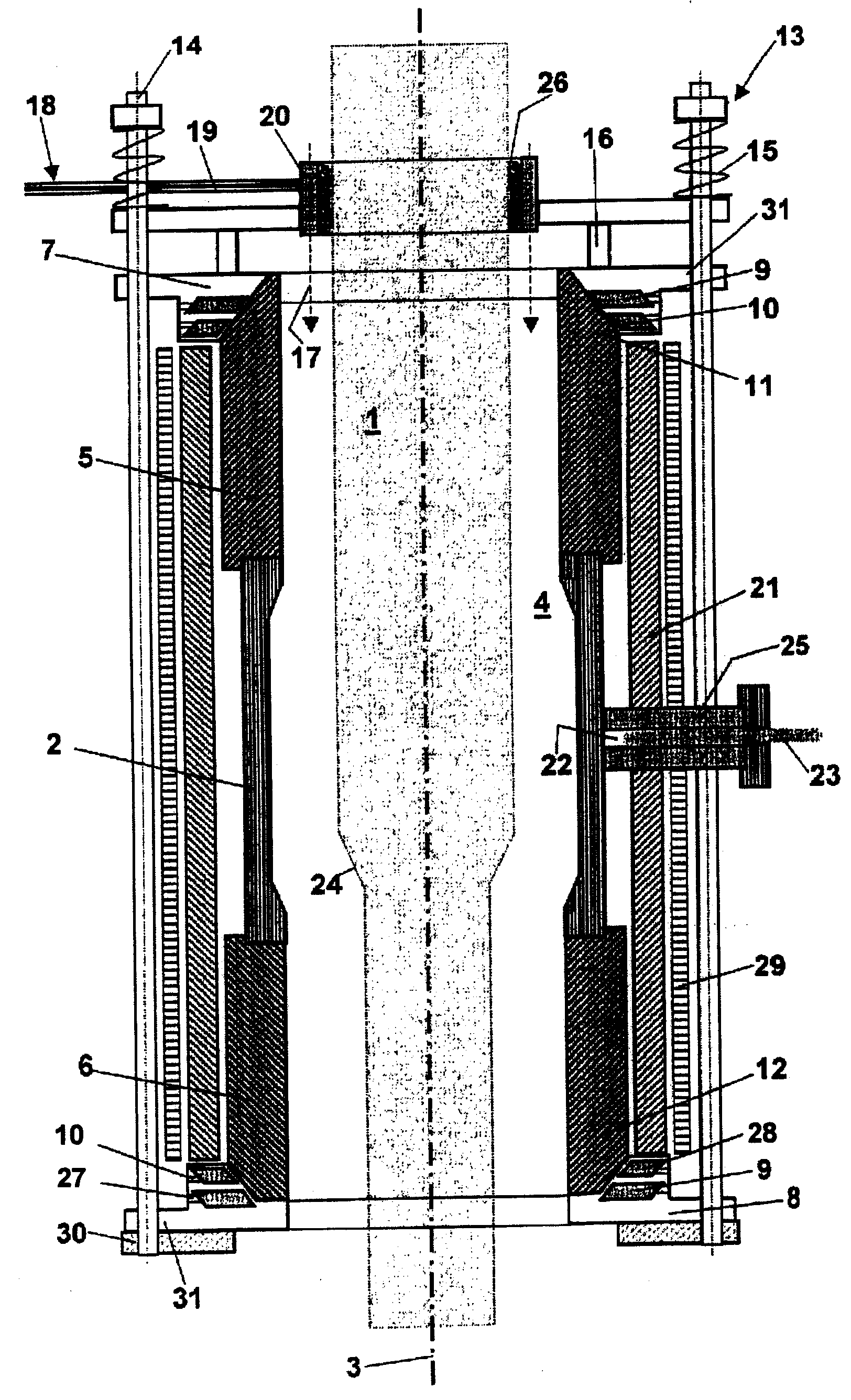
[0038] The electric resistance furnace shown in FIG. 1 of the present invention is used for heating and stretching a quartz glass cylinder 1 . This resistance furnace is a high-performance resistance furnace with a maximum heating capacity of 700kW. The electric resistance furnace comprises a graphite heating tube 2 with a vertically oriented longitudinal axis 3 , which encloses a heating chamber 4 .

[0039] The contact tubes 5, 6 are located at the front of the heating tube 2 on both sides. The contact tubes 5 , 6 are also made of graphite and have a greater wall thickness than the heating tube 2 .

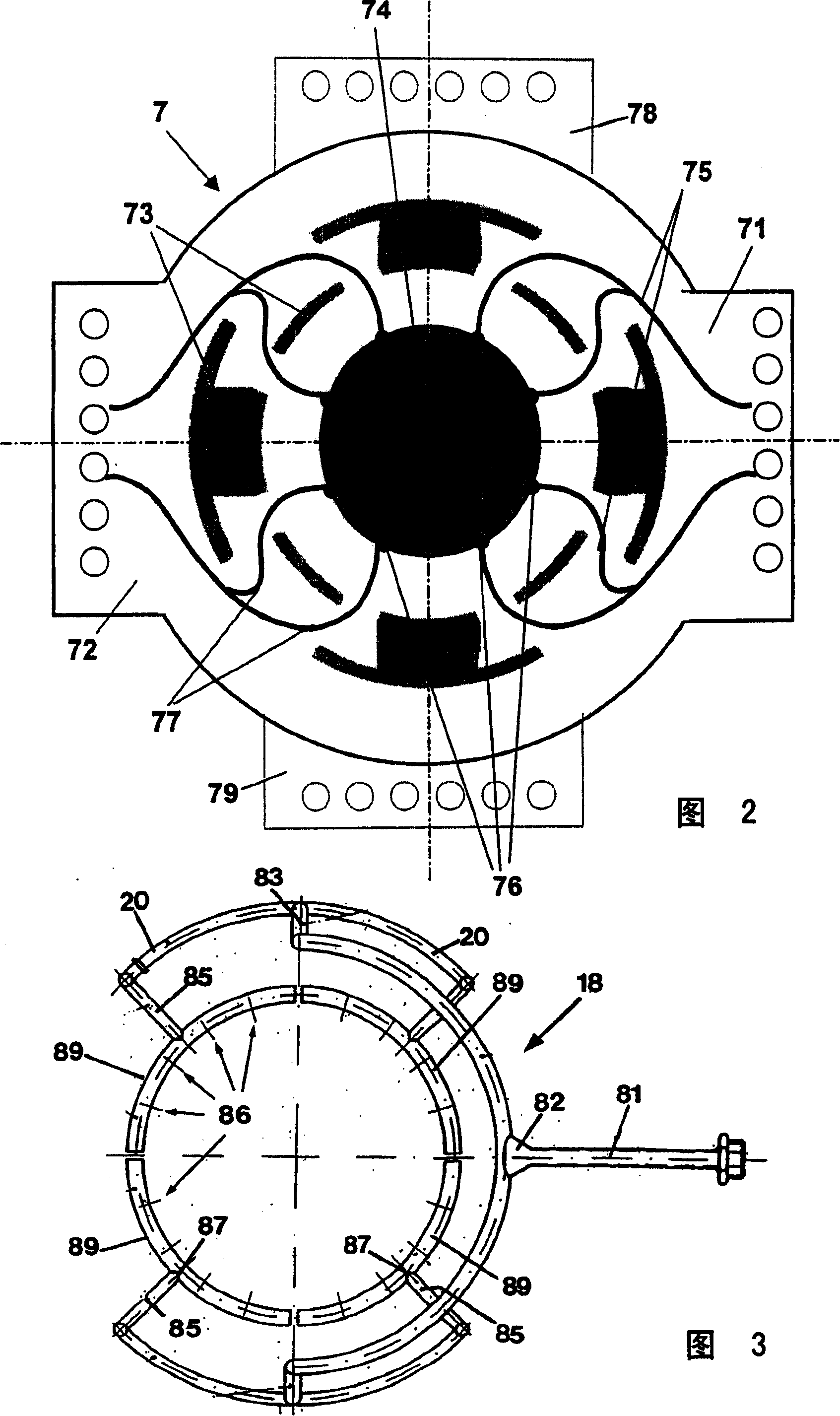
[0040] The current is introduced into the heating tube 2 through annular collars 7, 8, the annular collars are made of copper alloy CuCrZr, the upper annular collar 7 is located on the upper side 11 of the upper contact tube 5 and the lower annular collar 8 is located on the lower contact tube 6 underside 12 . The ring collars 7, 8 comprise outwardly protruding flanges 31 pro...


PUM


Abstract

A resistance furnace has a tubular heating element with a vertically-oriented longitudinal axis. The heating element has a shell surface defined by an upper side and a lower side and surrounding a furnace chamber. The heating element is connected to at least two supply terminals by which heating current is introduced at power supply points into the heating element. The supply terminals include a surrounding upper annular collar adjacent the upper side of the shell surface, and also a surrounding lower annular collar adjacent the lower side of the shell surface.

Description

technical field [0001] The invention relates to an electric resistance furnace comprising a tubular heating element with a vertical longitudinal axis, the element comprising a shell surface defined by an upper part and a lower part, and which surrounds a furnace chamber, and which The element is connected to a power supply terminal through which a heating current is introduced into the aforementioned heating element at the power supply point. Background technique [0002] High temperatures can be obtained with the help of electric resistance furnaces. Current flows through an ohmic resistor acting as a heat conductor, and the electrical energy is primarily converted into heat. Metals such as molybdenum, tantalum and platinum, ceramics, SiC or carbon variants such as coal, graphite or various glassy carbons (carbons produced by pyrolysis) are suitable as materials for the heat conductor. Graphite heat conductors are characterized by their high temperature resistance, simple...

Claims


Application Information

Patent Timeline
Patent Type & Authority Patents(China)
IPC IPC(8): F27D11/02H05B3/62F27B17/00H05B3/02F27B9/28F27D7/02F27D7/06F27D9/00F27D19/00F27D21/00F27D99/00H01L21/00
CPCF27D99/0073F27D21/0014C03B37/01257F27B17/00F27B9/28F27D2019/0025H01L21/67109F27D7/06F27D7/02C03B23/043F27D11/02F27D2009/0045H05B3/62F27D2099/001
Inventor T·博达恩O·冈茨
Owner HERAEUS QUARZGLAS
Why Eureka
Try Eureka