Beam splitter and beam combiner with isolated polarized beam

A beam splitter and beam combiner technology, applied in the coupling of optical waveguides, instruments, optics, etc., can solve problems such as poor optical coupling, and achieve the effect of less loss and small volume

Inactive Publication Date: 2002-08-21
JDS UNIPHASE CORP
View PDF0 Cites 30 Cited by
  • Summary
  • Abstract
  • Description
  • Claims
  • Application Information

AI Technical Summary

Problems solved by technology

If the tube is used to couple light from a crystal that is aligned with the focus of one of the beams, the other focus will not be at the tube end focus and there will be poor coupling of light from the e-ray or o-ray paths

Method used


Image

  • Beam splitter and beam combiner with isolated polarized beam
  • Beam splitter and beam combiner with isolated polarized beam
  • Beam splitter and beam combiner with isolated polarized beam

Examples


Embodiment 200

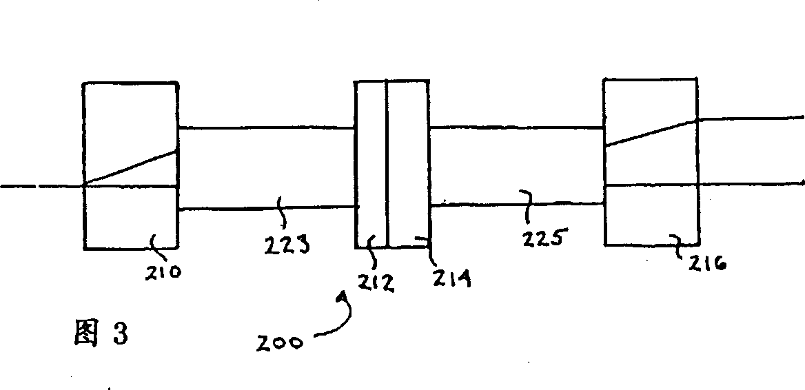
[0033] Fig. 3 is the further embodiment 200 of the present invention, and it comprises lens 223,225, is used for accepting the sub-beam from first crystal 210 and collimating the sub-beam directed to irreversible rotator 212,214, and when light passes through second Crystal 216 previously refocuses the sub-beams. Since the light from the crystal diverges and is no longer a point source, less than a quarter height span ratio gradient index (GRIN) lens can be used. Of course, other aspheric lenses can also be used. Advantageously, since the amplification ratio is 1:1, the coupling can be improved.

[0034] Figure 4a shows another embodiment of a polarizing beam splitter 250 with isolation. The first crystal 252 splits the orthogonally polarized light into sub-beams. Single crystal 252 is sized to provide effective beam spacing. The sub-beams pass through a half-wave plate 254 with an optical axis of 22.5° and a Faraday rotator 256, which together rotate the sub-beams 90° in ...


PUM


Abstract

The present invention relates to an isolated polarization beam sputter or combiner, for joining light from different inputs into one common port, or for dividing a beam of light into orthogonal polarizations. In both modes of operation, the splitter / combiner provides isolation preventing transmission of light in a reverse direction. As a sputter, a beam of light is separated through a birefringent material into sub-beams of orthogonal polarization components, and each sub-beam is passed through a non-reciproca l polarization rotator to rotate the polarization so that a reflected beam, or other counter- transmitted light cannot return on the same path through the birefringent material to the source. As a combiner, two separate beams of light are launched with known orthogonal polarizations into a first birefringent material, passed through a non- reciprocal polarization rotator and then combined as orthogonal polarizations into a single output port.

Description

field of invention [0001] The present invention relates to a polarizing beam splitter or combiner with isolation for combining light from different input ports into a common port and for splitting a beam of light into orthogonally polarized lights. In both modes of operation, the beam splitter / combiner provides efficient coupling in the direction of transmission, as well as isolation from light transmission in the reverse direction (isolation direction). Background of the invention [0002] Polarization-independent devices such as optical circulators and isolators typically require splitting an input beam of unknown polarization state into two orthogonally polarized sub-beams. These sub-beams pass through isolating elements of devices such as reciprocal and non-reciprocal rotators and are combined at the output. However, if the beam is emitted backwards, the irreversible element ensures that light does not feed back into the input. It is well known that rutile crystals, as...

Claims


Application Information

Patent Timeline
Patent Type & Authority Applications(China)
IPC IPC(8): G02B6/32G02B6/34G02B27/28
CPCG02B6/272G02B6/32G02B27/283G02B6/2773G02B6/2746
Inventor 冈扎隆·威尔斯皮埃尔·D·威尔常克怀金方宏王兴隆
Owner JDS UNIPHASE CORP
Why Eureka
Try Eureka