Constant force spring support hanger frame whose supporting and hanging forces and displacement do not change and loading force can be regulated

A technology with constant direction and constant force springs, applied in the directions of pipeline supports, instrument parts, instruments, etc., it can solve the problems that the bearing force cannot be kept constant, the stable work is unfavorable, and the adaptability is not strong, and the implementability is achieved. Strong, automatic balance medium reaction force, cleverly conceived effect

Inactive Publication Date: 2002-09-04
帖德顺
View PDF2 Cites 17 Cited by
  • Summary
  • Abstract
  • Description
  • Claims
  • Application Information

AI Technical Summary

Problems solved by technology

[0004] The applicant has found in practice that since the force generated by the deformation of the spring obeys Hooke's theorem, the bearing force (whether it is a supporting force or a suspension force) on all the load parts in the prior art cannot actually be kept constant. Because when the slewing frame is in the process of reciprocating rotation, the corresponding deformation of the spring is large or small, and the bearing force associated with it must be la...

Method used


Image

  • Constant force spring support hanger frame whose supporting and hanging forces and displacement do not change and loading force can be regulated
  • Constant force spring support hanger frame whose supporting and hanging forces and displacement do not change and loading force can be regulated
  • Constant force spring support hanger frame whose supporting and hanging forces and displacement do not change and loading force can be regulated

Examples


Embodiment 1

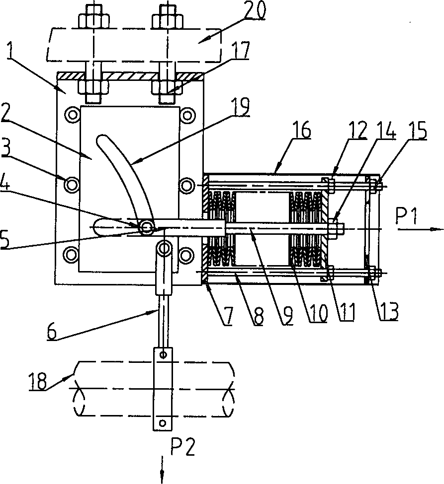
[0027] This example figure 1 As shown, it is mainly composed of a fixed frame (1), a rectangular displacement plate (2), a guide wheel (3), a roller (4), a disc spring pull plate (5), a boom (6), a front pressure plate (7), and a guide Rod (8), disc spring pull rod (9), disc spring group (10), rear pressure plate (11), pre-compression nut (12), fixed plate (13), compression nut (14), fixed nut ( 15), shell (16), fixed rooting bolt (17), displacement groove (19) and other components.

[0028] In this embodiment, the disc spring group (10) corresponds to the spring energy storage part in the technical solution, the disc spring pull plate (5) corresponds to the load coupling part, and the suspender (5) corresponds to the load transmission part. 6). The disc spring group (10) is clamped by the front and rear pressure plates (7, 11) and the pre-compression nut (12) on the guide rod (8) is locked according to the preloaded height of the disc spring group (10), Be fixed on one sid...

Embodiment 2

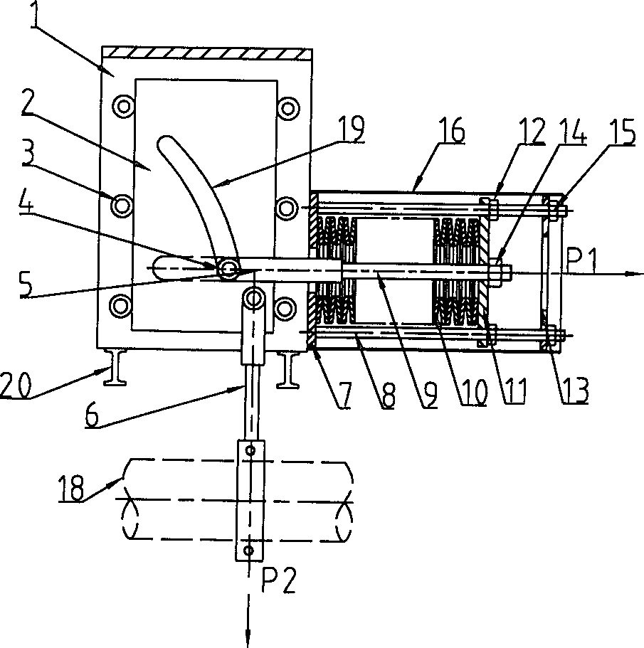
[0036]This example figure 2 As shown, it can be called a flat constant force disc spring seat hanger, and its structure and working principle are basically the same as those in Embodiment 1. The difference is that during installation, the lower end of the fixed frame (1) is supported on the I-beam (20).

Embodiment 3

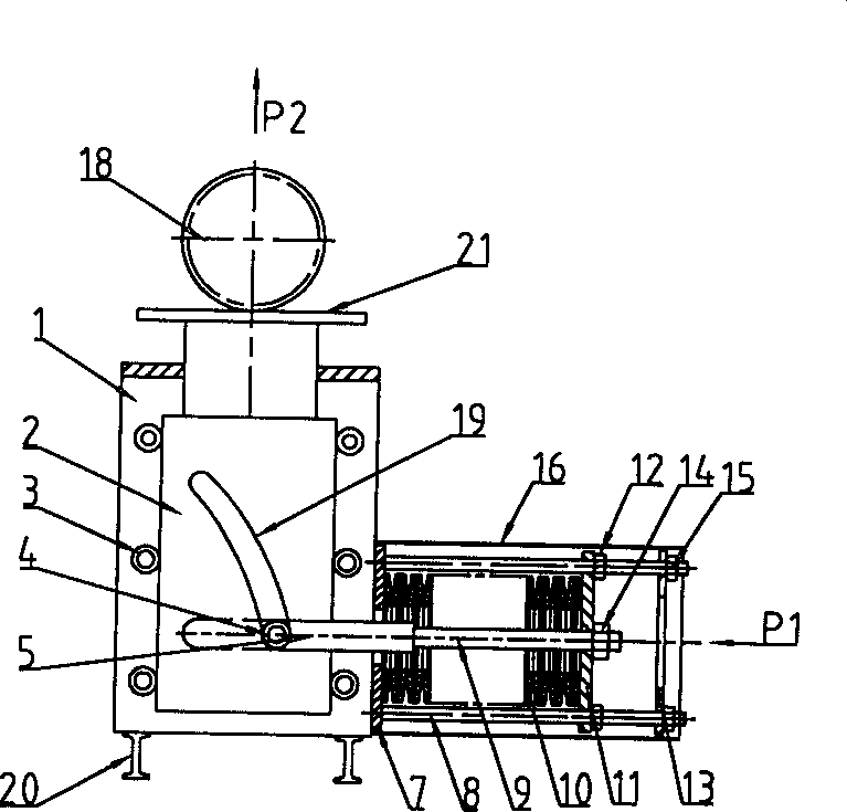
[0038] This embodiment is a flat constant force disc spring support, and its structure is as follows image 3 Shown, also basically the same as embodiment one, fixed frame (1) and figure 2 Similarly, the lower end of the fixed frame (1) is supported on the I-beam (20). The difference is that the load transmission part is not a suspension rod, but a support plate (21), and the pipeline or other load equipment (18) is supported above the support plate (21).


PUM


Abstract

The constant pressure spring support hanger frame is mainly formed from fixed frame, load coupling component, load force-transfer component and spring energy-storing component. One end of the described load coupling component is connected with spring energy-storing component. Besides, it also includes a displacement plate fixed in the fixed frame by means of motion pair, and said displacement plate is equipped with load force-transfer component and curve contour capable of retaining loading direction and acting force constant, said curve contour is connected with another end of load coupling component.

Description

technical field [0001] The invention relates to a spring support and hanger, in particular to a constant force spring support and hanger, which belongs to the field of thermal pipeline and equipment support and hanger devices. Background technique [0002] As we all know, thermal expansion and contraction of objects will cause thermal displacement of pipelines in industries such as electric power, petroleum, and chemical industries, and catenary lines in industries such as electrified railways. In order to ensure this thermal displacement so that pipelines and network cables can work normally, constant force spring supports and hangers are widely used in the above-mentioned industries. [0003] The existing constant force spring hanger is mainly composed of a fixed frame, a revolving frame hingedly mounted on the fixed frame and a spring. Among them, the supporting end of the slewing frame is connected with the pipeline or network cable that needs to be loaded, and the othe...

Claims


Application Information

Patent Timeline
IPC IPC(8): F16L3/00F16L3/16F16L3/205G12B9/08
Inventor 帖德顺
Owner 帖德顺
Why Eureka
Try Eureka