Sewage treatment equipment

A technology of sewage treatment device and sewage treatment tank, which is applied in water/sewage treatment, biological water/sewage treatment, flotation water/sewage treatment, etc., and can solve problems such as no consideration.

Inactive Publication Date: 2002-10-02
SANYO ELECTRIC CO LTD
View PDF3 Cites 1 Cited by
  • Summary
  • Abstract
  • Description
  • Claims
  • Application Information

AI Technical Summary

Problems solved by technology

[0003] In this way, in the previous sewage treatment equipment, the air diffusion pipe was widely used as

Method used


Image

  • Sewage treatment equipment
  • Sewage treatment equipment
  • Sewage treatment equipment

Examples


Embodiment Construction

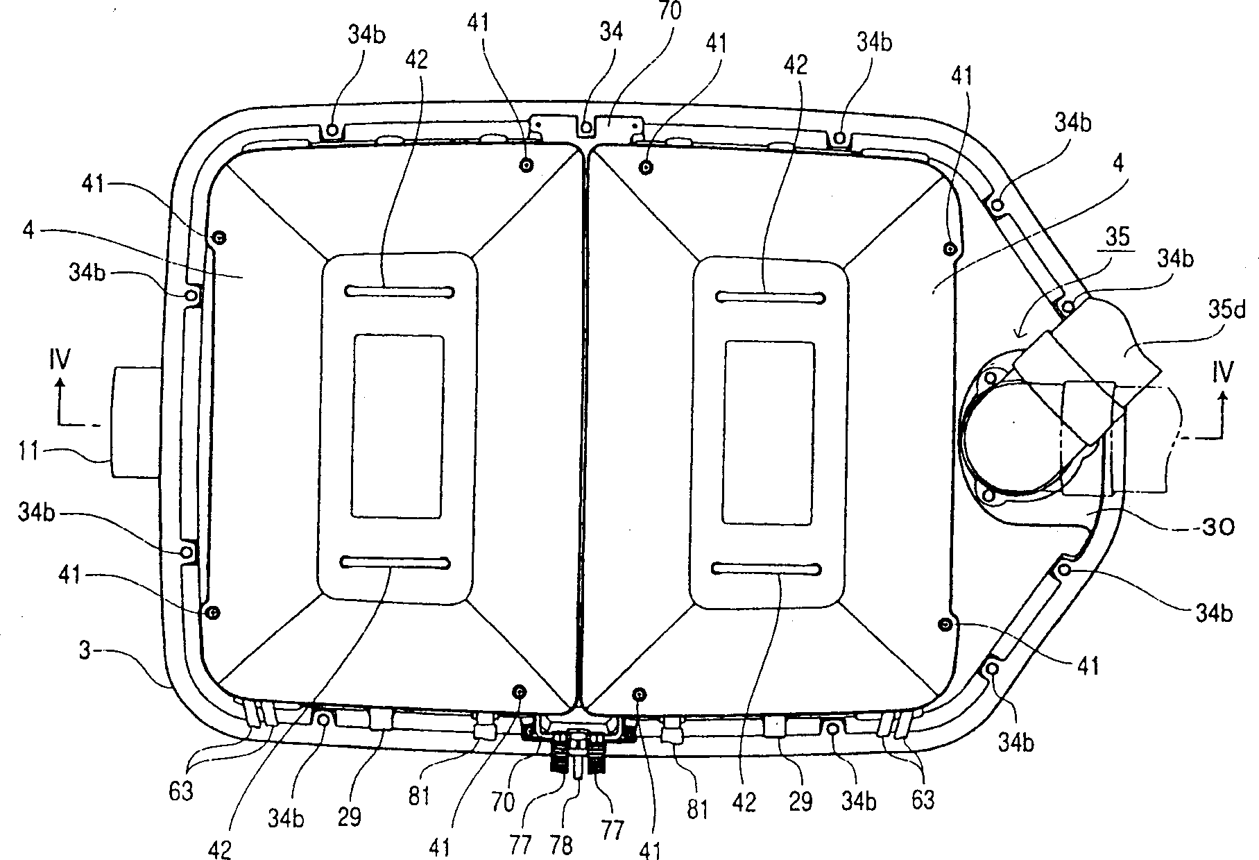
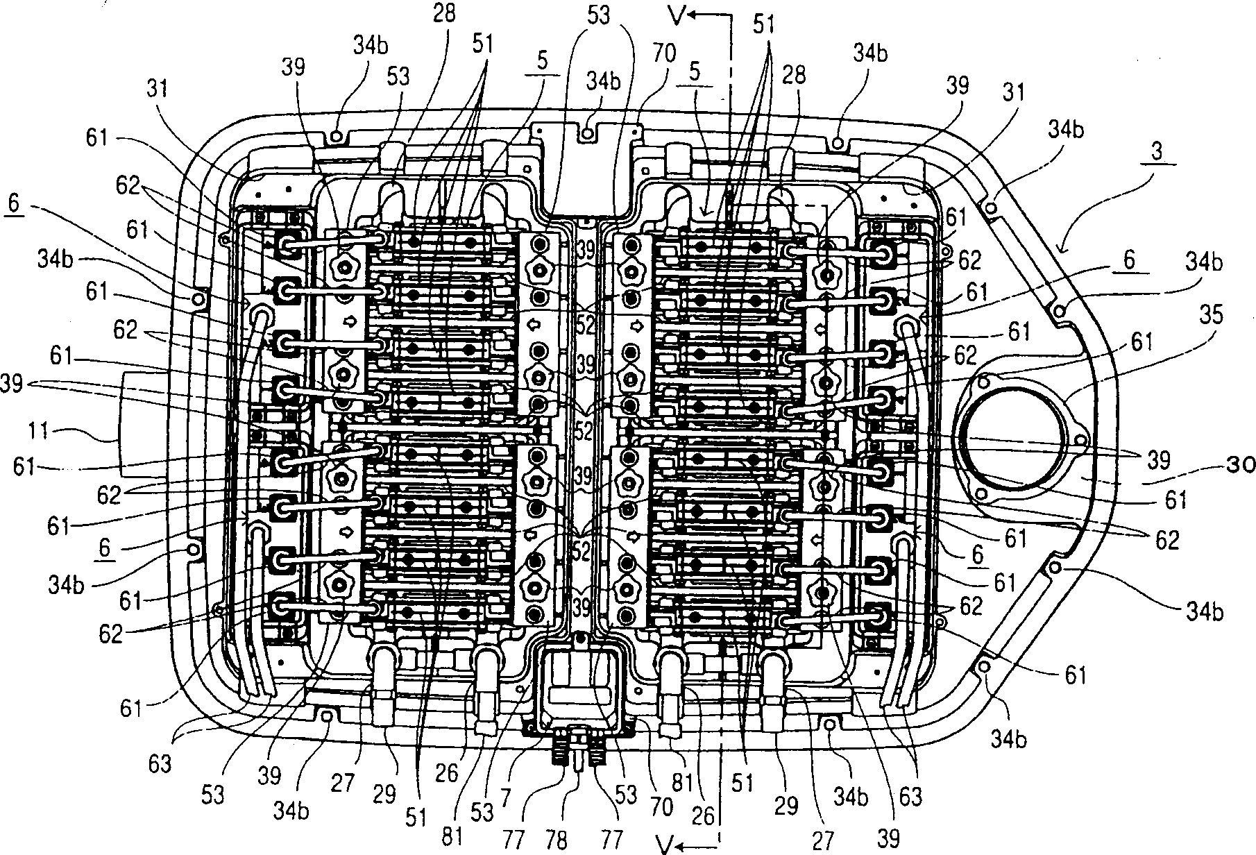
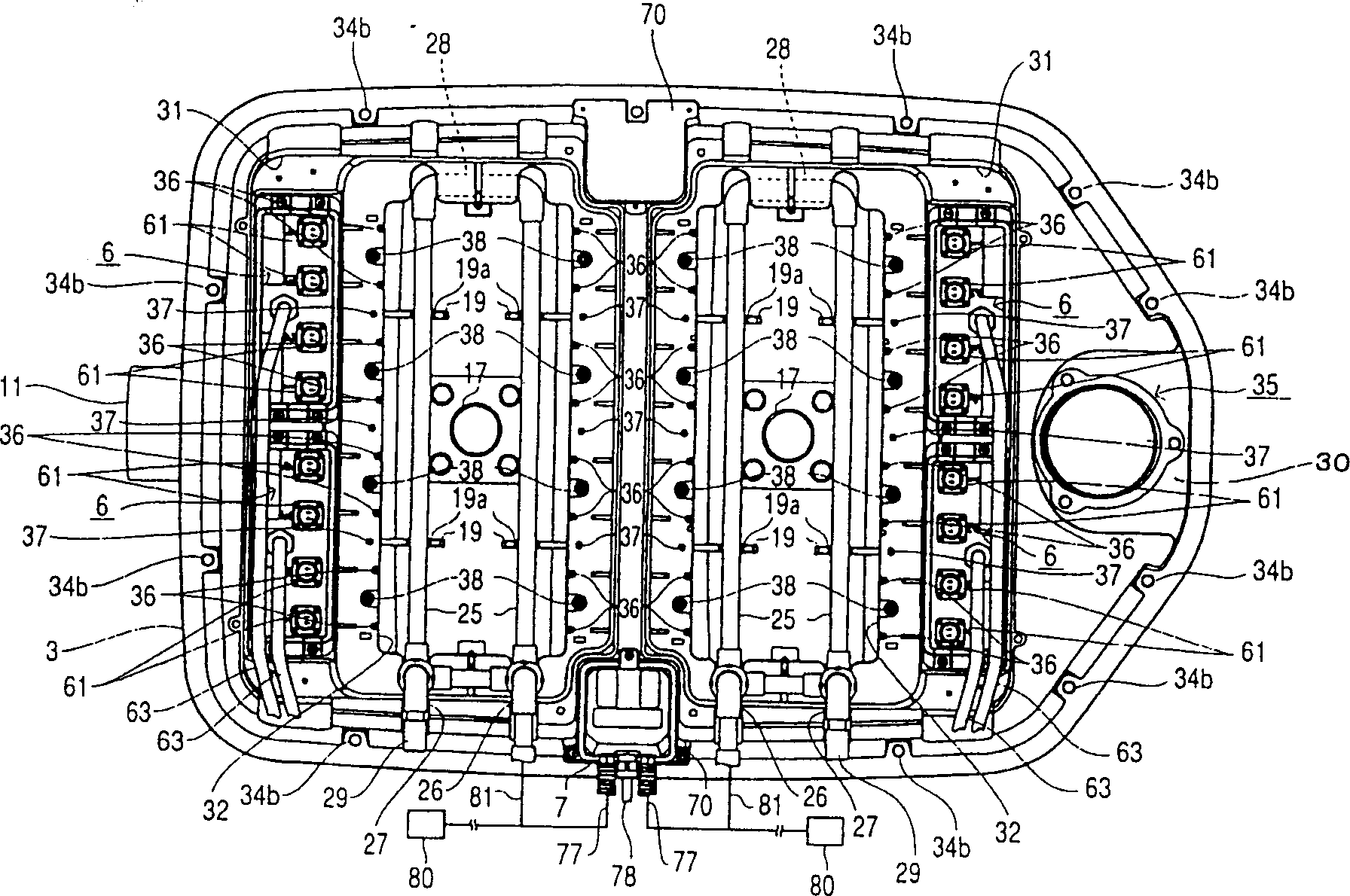
[0032] The following is based on Figure 1 to Figure 7 Embodiments in which the electrolytic cell for sewage treatment equipment according to the present invention is embodied will be described. in addition, figure 1 It is an appearance plan view of an electrolytic cell related to this embodiment, figure 2 It is a plan view of the state where the upper cover of the electrolytic cell related to this embodiment is removed, image 3 It is a plan view of the state where the upper cover and the electrode unit of the electrolytic cell related to the present embodiment are removed, Figure 4 for figure 1 The IV-IV sectional view in . And, in the Figure 4 In the figure, the electrode units on the side of the sewage outlet are shown as the state where the partition plate can be seen, and the electrode units on the side of the sewage inlet are shown as the state where the side of the electrode unit row can be seen. and, Figure 5 for figure 2 The V-V section diagram in, Fig...


PUM


Abstract

A sewage treatment device capable of detecting failure of an air diffuser pipe, equipped with a sewage treatment tank for treating sewage, and a system for blowing air supplied from a blower into the sewage in the sewage treatment tank or The sewage treatment device of multiple systems of air diffusion pipes is further equipped with one or more systems of pressure sensors for detecting abnormal pressure on the inlet side of the one or more systems of air diffusion pipes.

Description

technical field [0001] The present invention relates to a sewage treatment device, and more specifically relates to a sewage treatment device equipped with an air diffusion pipe. Background technique [0002] Air diffuser pipes have been used for various purposes in conventional sewage treatment plants. For example, in the integrated treatment purification tank described in JP-A-10-192869, a total of five air-air diffuser pipes of No. 1 to No. 5 are used. The first air diffusion pipe is used in the contact blowing tank to keep the contact blowing tank in an aerobic state, and decompose the water through aerobic microorganisms, and decompose ammonia nitrogen into nitric acid and nitrous acid through the action of nitric acid bacteria and nitrous bacteria Sexual nitrogen. The second air diffusion pipe is also used in the contact blowing tank to peel off the biofilm attached to the contact material, proliferating and gradually thickening. The 3rd air diffuser pipe is arrange...

Claims


Application Information

Patent Timeline
IPC IPC(8): C02F3/20C02F1/461C02F1/463C02F1/465C02F1/74C02F3/12G08B21/00
CPCY02W10/10C02F1/74
Inventor 福永武士小田谦治福本明广奥见敏喜
Owner SANYO ELECTRIC CO LTD
Why Eureka
Try Eureka