Camera

A camera device and the technology of the camera department, which are applied in image communication, television, color TV, etc., can solve the problems of appearance shape and color restrictions, large swing radius, and inability to freely design

Inactive Publication Date: 2002-10-16
PANASONIC CORP
View PDF1 Cites 3 Cited by
  • Summary
  • Abstract
  • Description
  • Claims
  • Application Information

AI Technical Summary

Problems solved by technology

[0012] (1) The spherical semicircular cover covers the whole device, so the shape and color of its appearance are limited, and it cannot be freely designed
[0013] (2) The swing axis of the camera body is set at the rear end of the camera body, and the swing radius of the camera

Method used


Image

  • Camera
  • Camera
  • Camera

Examples


no. 1 Embodiment

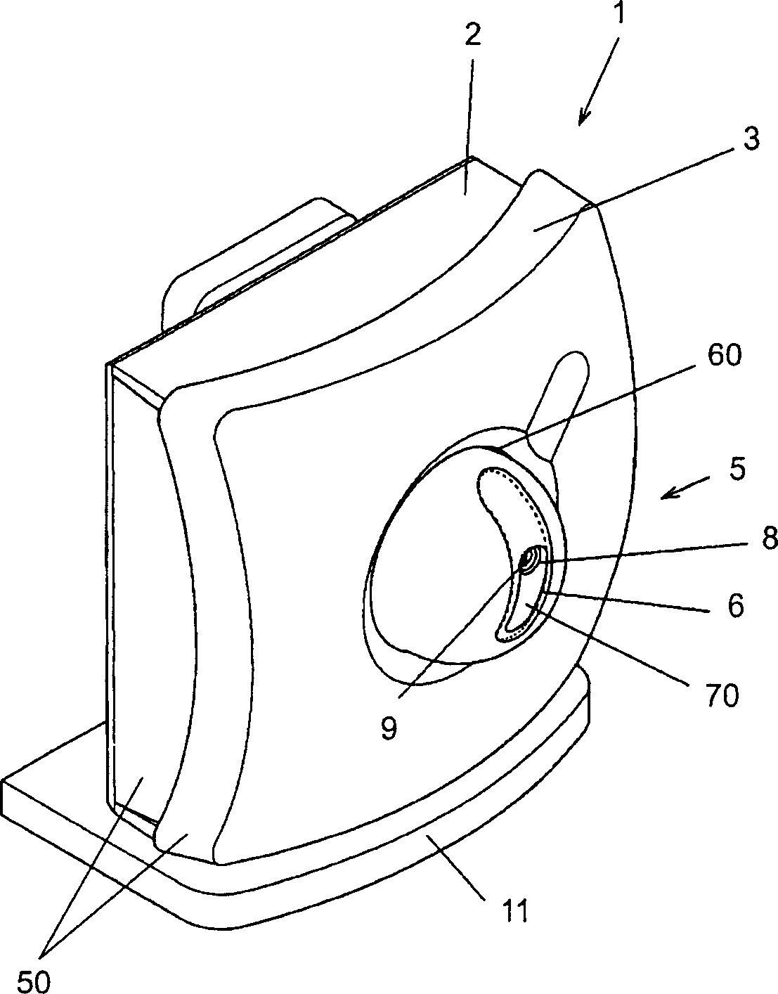
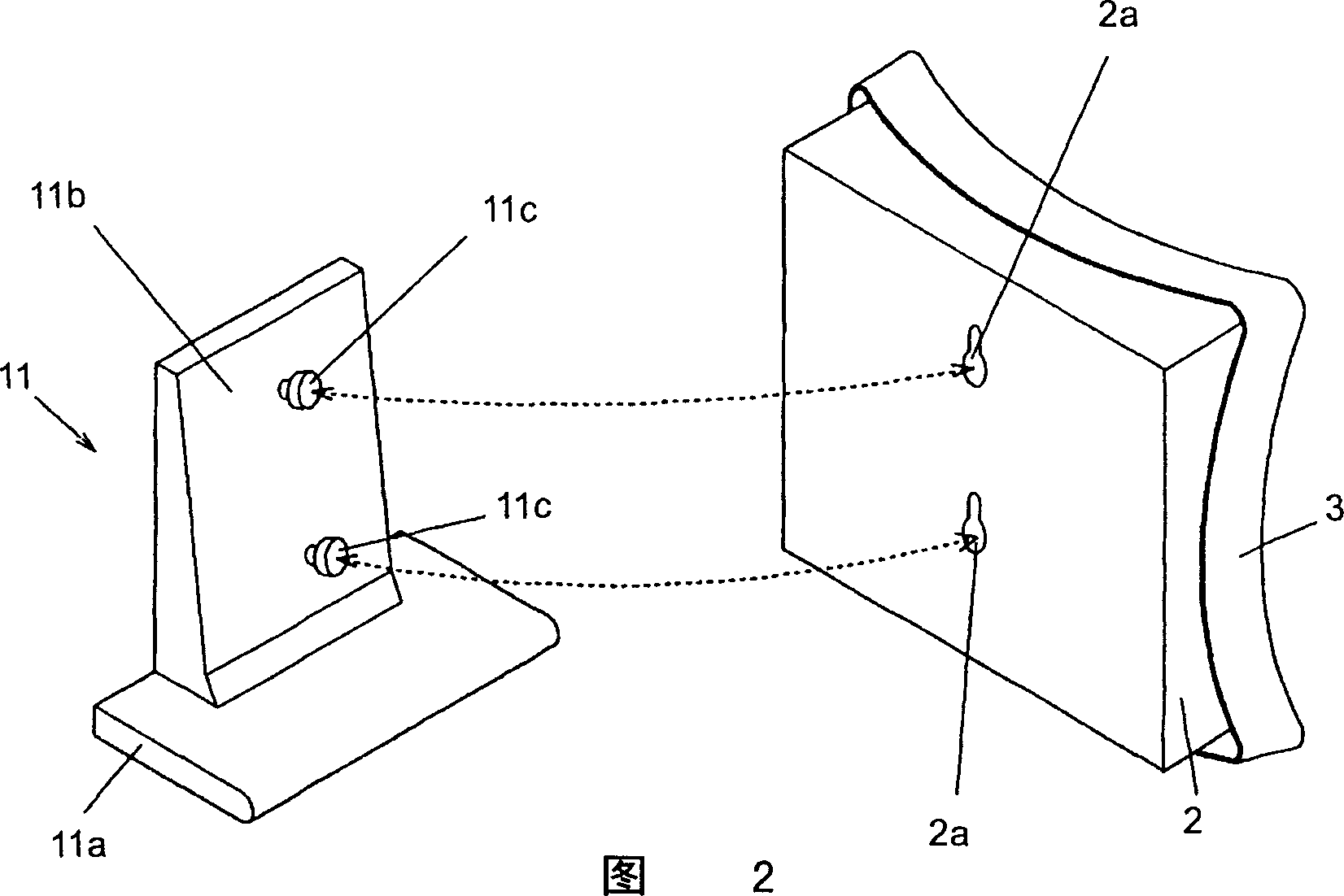
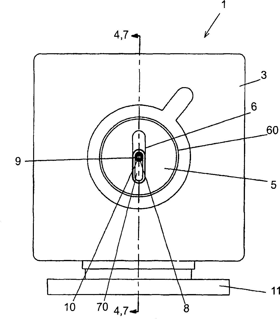
[0045] figure 1 It is a three-dimensional view of the main part of the imaging device of the embodiment of the present invention, and Fig. 2 is figure 1 A perspective view of main parts of the camera device shown before installation of the camera support base, image 3 for figure 1 A front view of the main part of the camera unit shown.

[0046] exist figure 1 ,figure 2, image 3 Among them, the imaging device 1 of the first embodiment of the present invention includes a box-shaped base 2 with one side open. Hook holes 2 a are drilled in the upper and lower parts of the back of the base 2 , and the cover 3 is fitted into the opening of the base 2 . The base 2 and the cover 3 constitute the housing 50 of the imaging device 1 .

[0047] A substantially circular hole 60 is drilled in substantially the center of the cover portion 3 . The hollow spherical panning part 5 provided inside the cover part 3 passes through the hole part 60 , and a part protrudes from the cover part...

no. 2 Embodiment

[0096] figure 1 It is a perspective view of the main part of the camera device of the embodiment of the present invention, and FIG. 2 shows figure 1 A perspective view of the main parts of the state before the support base of the camera unit is installed, image 3 yes figure 1 A front view of the main part of the camera unit shown. Figure 7 is the camera device of the second embodiment of the present invention according to image 3 Sectional view of the position indicated by the center line 7-7.

[0097] In this second embodiment, the imaging device differs from that of the above-mentioned first embodiment only in the tilt drive unit. thereby, Figure 1 to Figure 3 Similar to the above-mentioned first embodiment, description is omitted.

[0098] exist Figure 7 Among them, the camera device 1, the base 2, the hook hole 2a, the cover part 3, the opening part 60, the panning part 5, the outer image incident part 6, the pitch surface 70, the inner image incident part 8, t...


PUM


Abstract

The imaging device of the present invention includes: a casing part, a panning part having an outer image incident part, a panning shaft, a panning shaft supporting part, a panning part driving device for rotating the panning part around the panning shaft, It has a pitch portion of the pitch plane of the inner image incident portion, a pitch axis, a pitch portion driving device that rotates the pitch portion around the pitch axis, and an imaging portion provided inside the pitch portion. By adopting this structure, the provided camera device can visually capture the camera action, and because the internal mechanism is concealed, the degree of freedom of design is improved. In addition, the useless space inside the device can be reduced, and the device can be miniaturized.

Description

technical field [0001] The invention relates to a camera device for anti-theft, monitoring, monitoring and observation. It can visually capture the dynamics of the image incident part, and has a simple structure. Background technique [0002] In recent years, in order to monitor, monitor and observe, etc., or to prevent theft, banks, shops, amusement parks, etc. have widely adopted camera devices such as CCDs installed on ceilings, floors, and walls of surveillance places. Such an imaging device has a mechanism for panning the camera in the horizontal direction and a tilting operation for rotating the camera in the vertical direction. With this mechanism, it is possible to point the camera in any direction from the installed position, thereby performing wide-area shooting. [0003] Such a conventional imaging device is disclosed in Japanese Utility Model Application, Utility Model Publication No. Hei 7-42261 (hereinafter simply referred to as a conventional example). This...

Claims


Application Information

Patent Timeline
IPC IPC(8): H04N5/225H04N5/232
CPCG08B13/19619G08B13/1963G08B13/19632H04N23/50H04N23/661H04N23/695
Inventor 田代祐幸相浦信次
Owner PANASONIC CORP
Why Eureka
Try Eureka