Cloth feeder of sewing machine

A cloth feeding device and sewing machine technology, which is applied to the sewing machine control device, sewing machine components, cloth feeding mechanism, etc., can solve problems such as hindering the straightness of cloth, and achieve the effect of improving quality

Inactive Publication Date: 2002-10-30
JUKI CORP
View PDF1 Cites 11 Cited by
  • Summary
  • Abstract
  • Description
  • Claims
  • Application Information

AI Technical Summary

Problems solved by technology

Therefore, when the load switching occurs on the left and right feed teeth, the straightness of the cloth may be hindered.

Method used


Image

  • Cloth feeder of sewing machine
  • Cloth feeder of sewing machine
  • Cloth feeder of sewing machine

Examples


Embodiment 2

[0091] Embodiment 2 is different from Embodiment 1 in the left-right movement mechanism. The same symbols are attached to the other same places, so their descriptions are omitted.

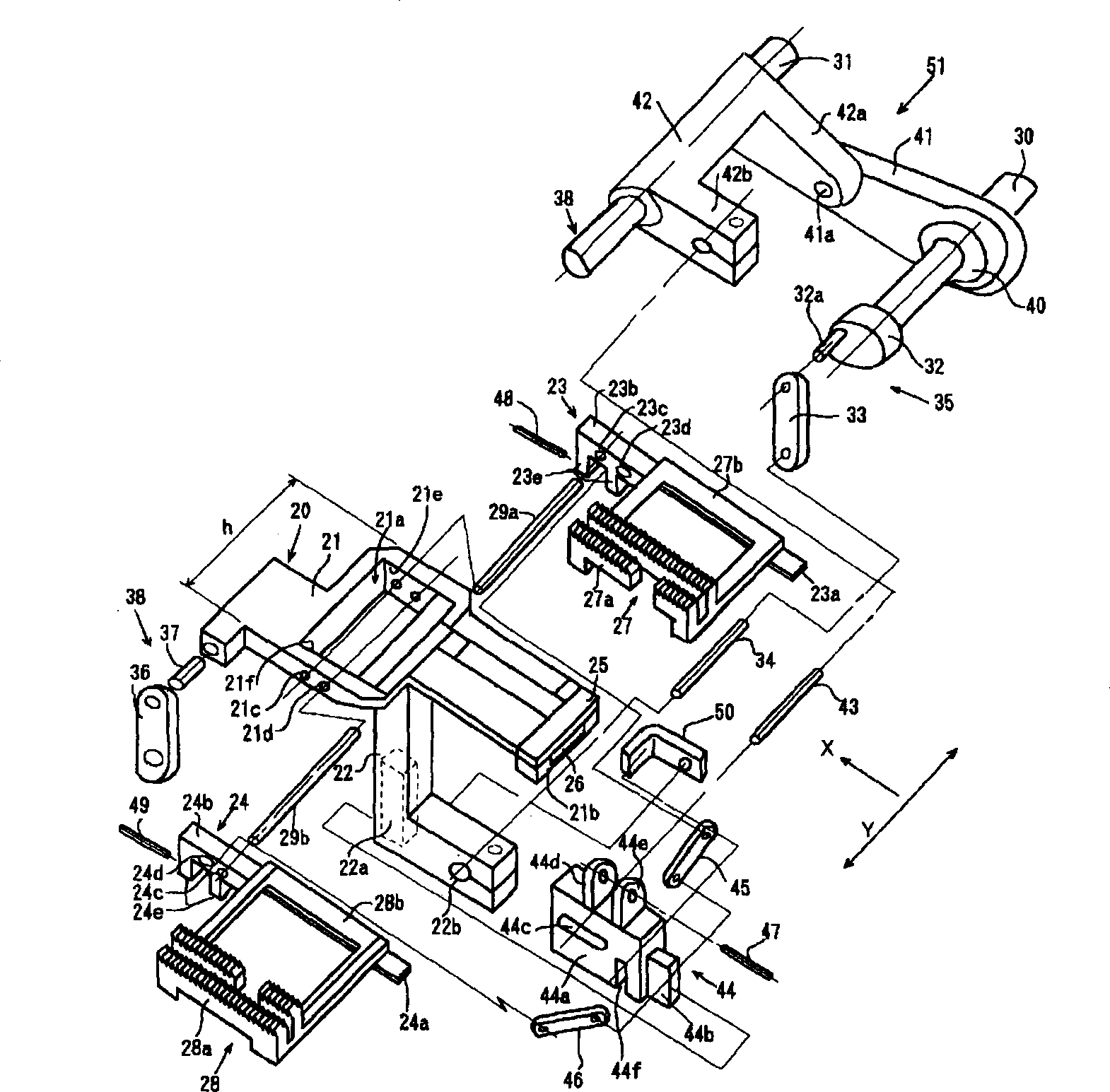
[0092] What constitute left and right moving mechanism 63 is: the motor 61 that is fixed on the sewing machine frame, the rocking plate 62 that is fixed on the output shaft of motor 61 and one end are fixed on the position that is positioned at the center of rotation separation from rocking plate 62, and the other end floats. The shaft 43 is fitted in the long hole 44c of the upper and lower body 44 .

[0093] When motor 61 rotates, then rocking plate 61 and axle 43 just shake, and upper and lower body 44 is moved along the up and down direction. As described in Embodiment 1, due to the vertical movement of the upper and lower body 44 and the relative movement of the cloth feed table 20 up and down, the left and right feed dog links 45, 46 are opened and closed, and the left and right feed teeth 2...

Embodiment 3

[0100] Example 3 is different from Example 1 in the support structure of the left and right feed dogs. The same symbols are assigned to other similar parts, so their explanations are omitted.

[0101] The left and right feed dogs are composed of a right feed dog 65 and a left feed dog 66 which are divided into two halves along the feed direction.

[0102] The right feed dog 65 is composed of a tooth portion 65a and a right holding portion 65b in a planar L-shape that holds one end side of the fixed tooth portion. The right end portion 65b is placed on the upper flat surface of the right feed dog stand 23, and is fixed with screws (not shown). Similarly, the left feed dog 66 is composed of a tooth portion 66a and a holding portion 66b. The left holding portion 66b is placed on the upper flat surface of the left feed dog stand 24 and fixed with screws (not shown).

[0103] The left and right cloth feeding teeth 65, 66 installed on the cloth feeding table 20 are connected with ...

Embodiment 4

[0106] In Example 4, compared with Example 1, the shapes of the support shafts and the support holes that guide the left and right feed dog stages in the sliding direction are different. The same symbols are attached to other common points, so their descriptions are omitted.

[0107] On the left and right feeding dog stages 23, 24, square pins 67, 68 are respectively fixed along the sliding direction. On the side surface of the cloth feeding table 20, there are square holes 21m and 21n penetrating in both directions along the sliding direction. The square holes 21m, 21n slidably support the respective square pins 67, 68, respectively. According to Embodiment 4, occurrence of deflection can be more reliably prevented.


PUM


Abstract

PURPOSE: Provided is a cloth feeding device which is compact and performs precise movement when moved in a sliding direction. CONSTITUTION: In the sewing machine cloth feeding device comprises left and right feed dogs(27, 28) consisting of right and left feed dogs which are divided along a cloth feeding direction, a feed bar(20) for supporting the left and right feed dogs to be movable in a direction crossing the cloth feed direction, a vertical driving means(35) for giving a vertical motion to the left and right feed dogs, a horizontal driving means(38) or giving a horizontal motion to the feed dogs and left and right driving means(63, an actuator) for giving a motion in a sliding direction which crosses the cloth feeding direction to the feed dogs, the device comprises a plurality of support shafts(29a) which are individually fixed to the left and right feed dogs and arranged along the sliding direction and a plurality of support holes(21c, 21d) which are formed at both ends of the feed bar in the sliding direction in order to support the support shafts so as to be independently movable along the sliding direction.

Description

technical field [0001] The present invention relates to a cloth feeding device of a sewing machine, in particular capable of imparting movement to left and right cloth feeding teeth in a direction intersecting the cloth feeding direction. Background technique [0002] In the past, the cloth feeding device of this sewing machine is known as a device that moves the left and right cloth feeding teeth in the sliding direction in isolation from each other during cloth feeding, as described in the Japanese Patent Application Publication No. 2000-271364 previously applied by the applicant. . Figure 11 The device shown has: a U-shaped cloth feed table 1, a cloth feed dog 2 and a cloth feed dog table 3 mounted on the cloth feed table 1, and one end side is fixed on the left and right feed dog tables 2 and 3, At the same time, the holding parts 6, 7 of the left and right cloth feed teeth 4, 5 and the rotary hook 8 disposed below the central notch of the cloth feed table 1 are respect...

Claims


Application Information

Patent Timeline
Patent Type & Authority Applications(China)
IPC IPC(8): D05B27/02D05B3/04
CPCD05B3/04D05B27/02D05B33/00D05B35/02D05B69/30
Inventor 秋山辰仁
Owner JUKI CORP
Why Eureka
Try Eureka