Supercharge Your Innovation With Domain-Expert AI Agents!

Light deflection optical system

An optical system and light deflection technology, applied in optics, optical components, printing, etc., can solve problems such as high cost, no consideration of deflection beam rotation, difficult processing, etc., and achieve the effect of easy processing

Inactive Publication Date: 2002-11-13
SEIKO EPSON CORP
View PDF2 Cites 4 Cited by
  • Summary
  • Abstract
  • Description
  • Claims
  • Application Information

AI Technical Summary

Problems solved by technology

[0004] However, in Japanese Patent Laid-Open No. 51-6563, in order to avoid interference between the two fixed plane mirrors and the incident light beam and the outgoing light beam, there is the problem of the so-called light deflection angle becoming smaller.
[0005] In Japanese Patent Laid-Open No. 61-7818, when the deflection reflection surface is composed of rotating polygon mirrors, etc., the in-and-out of the rotation axes of each deflection reflection surface due to the eccentricity of the rotation axis of the deflection reflection surface, etc., is not considered, causing scanning lines. Changes in spacing, etc.
[0006] In addition, issues such as deflected beam rotation around the scan line are not considered
[0007] In the light deflection optical system of JP-A No. 61-7818, since a fixed flat mirror is inserted between the light beam incident on the light deflection optical system and the reflected deflected light beam, it is actually necessary to use a high-precision flat mirror with an extremely narrow width. , there is also the problem of difficult processing and high cost

Method used


Image

  • Light deflection optical system
  • Light deflection optical system
  • Light deflection optical system

Examples


Embodiment Construction

[0047] The principle and examples of the light deflecting optical system of the present invention will be described in detail below with reference to the accompanying drawings.

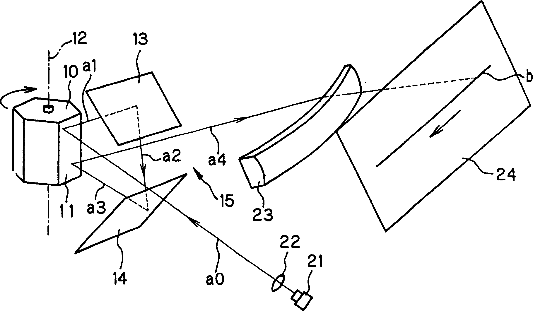
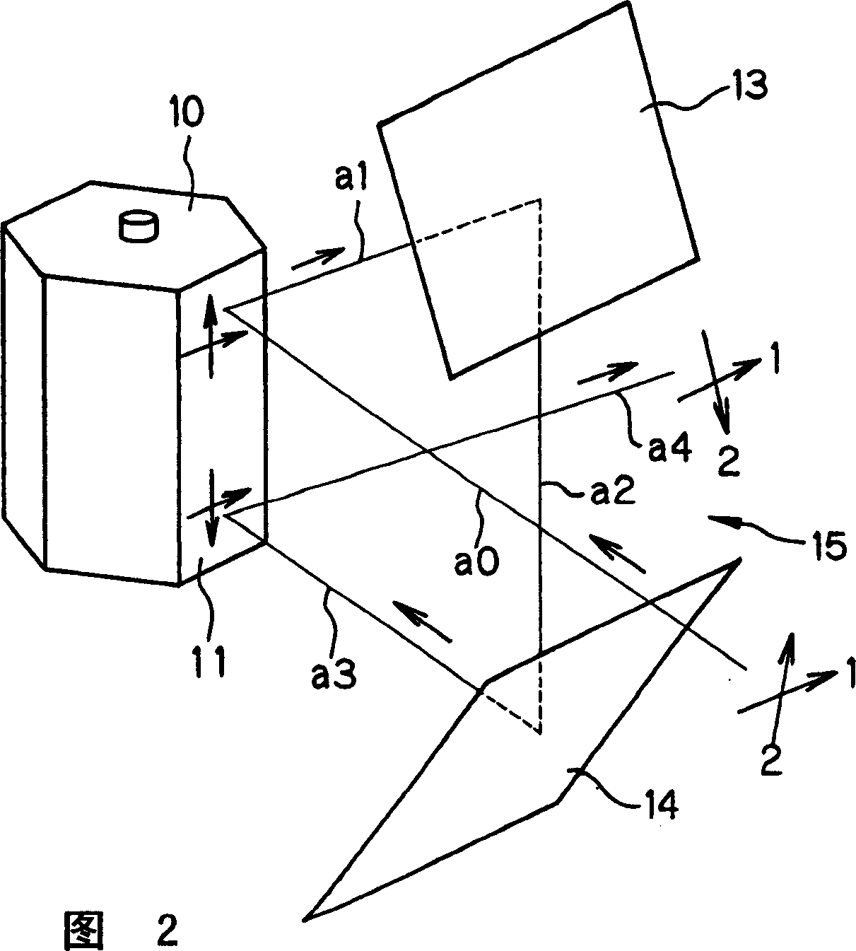
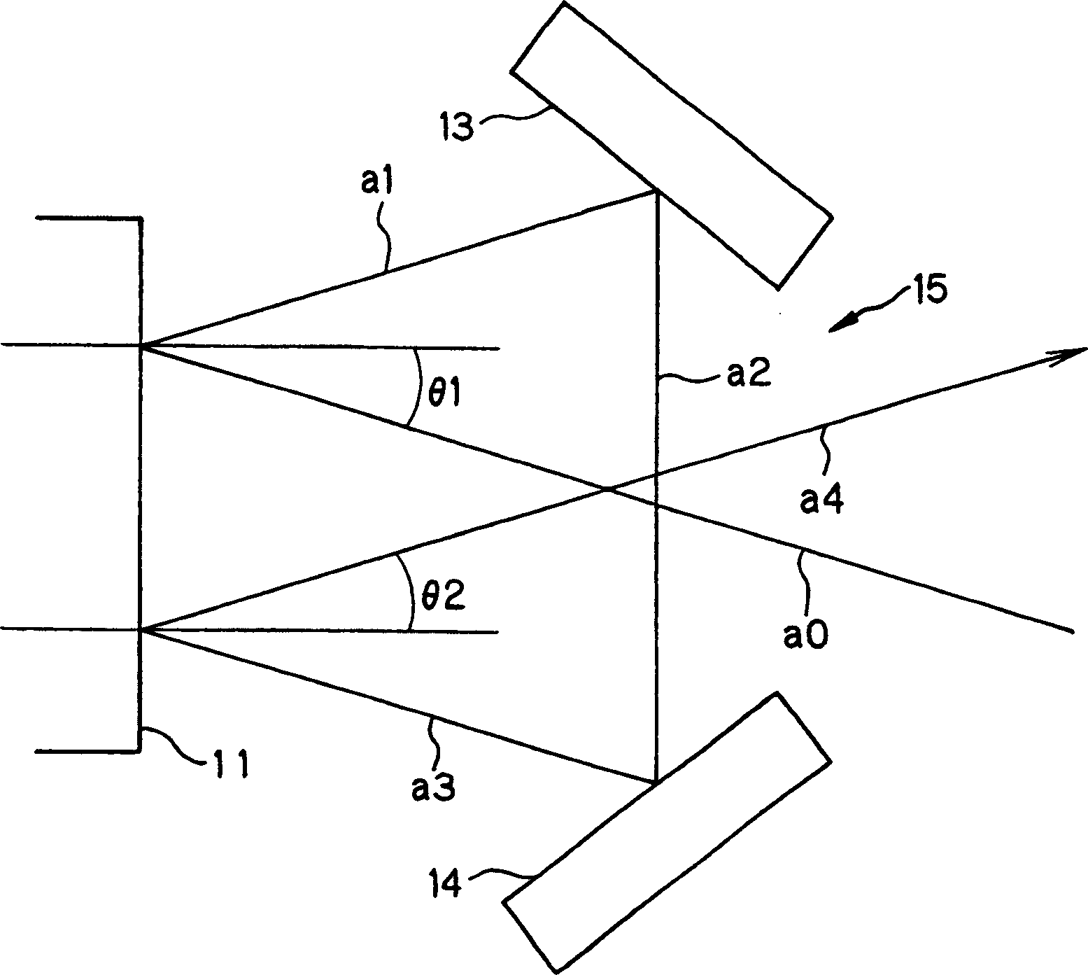
[0048] figure 1 is a perspective view showing the overall configuration of an optical scanning device including the light deflecting optical system of the present invention, and FIG. 2 is a perspective view showing the main part of the light deflecting optical system.

[0049] According to this configuration, the light deflection unit is composed of a polygon mirror 10 having a plurality of (six in the figure) deflection reflection surfaces 11 on the side surfaces of the polygon cylinder, and the deflection reflection surface 11 is formed to rotate around the axis of the polygon mirror. structure. Furthermore, facing the deflection reflection surface 11 related to light deflection, two fixed flat mirrors 13 and 14 are arranged at an angle to each other with a gap 15 opened therebetween.

[0050]The ...


PUM


Abstract

The present invention relates to a light deflection optical system which does not use a flat mirror with a narrow width, does not cause a change in the scanning line pitch even if there is an in-and-out on the deflection reflection surface, and does not twist the deflected beam. The deflecting reflective surface 11 is configured with fixed plane mirrors 13 and 14, incident on the deflecting reflective surface, the reflected light beam a1 is reflected on the fixed plane mirror, the reflected light beam a3 enters the deflecting reflective surface again, and the reflected light deflecting optical system converts the light beam a1 including the initial incident When the plane parallel to the rotation axis 12 of the beam a0 on the deflecting reflective surface is used as the incident plane, the beam a0 is incident through the gap 15 between the fixed plane mirrors, and the deflected beam a4 reflected for the second time on the deflecting reflective surface is emitted through the gap 15.

Description

field of invention [0001] The present invention relates to a light deflection optical system for image writing and exposure in an image forming apparatus such as a laser beam printer, and more particularly to a light deflection optical system for sequentially incident light beams twice on a deflection reflection surface such as a rotating polygon mirror. technical background [0002] It was proposed in JP-A No. 51-6563 that two fixed flat mirrors are arranged on the rotating or vibrating deflecting reflective surface, and the deflected light beams reflected on the deflecting reflective surface are arranged sequentially on the two fixed flat mirrors. Reflection, and then deflect light by incident on its deflecting reflective surface, by skewing the rotation axis of the deflecting reflective surface or skewing the surface of each deflecting reflective surface to compensate for the change in the exit direction of the deflected beam. [0003] In addition, JP-A-61-7818 (U.S. Pate...

Claims


Application Information

Patent Timeline
Patent Type & Authority Applications(China)
IPC IPC(8): B41J2/44G02B26/10G02B26/12H04N1/036H04N1/113
CPCG02B26/129
Inventor 宗和健井上望铃木隆史
Owner SEIKO EPSON CORP
Features
  • R&D
  • Intellectual Property
  • Life Sciences
  • Materials
  • Tech Scout
  • Unparalleled Data Quality
  • Higher Quality Content
  • 60% Fewer Hallucinations
Learn More