Non-scanning 3D imaging laser radar optical system based on APD array

An APD array and lidar technology, applied in the field of non-scanning 3D imaging lidar optical systems and lidar optical systems, can solve the problems of high price, complex structure, inconvenient adjustment, processing and maintenance, etc., and achieves easy processing and improved angular resolution. rate, the effect of reducing the background

Inactive Publication Date: 2009-05-13
BEIHANG UNIV
View PDF0 Cites 38 Cited by
  • Summary
  • Abstract
  • Description
  • Claims
  • Application Information

AI Technical Summary

Problems solved by technology

[0005] The purpose of the present invention is to provide a non-scanning 3D imaging laser radar optical system based on APD array, which overcomes the shortcomings of existing laser radar optical systems, such as co

Method used


Image

  • Non-scanning 3D imaging laser radar optical system based on APD array

Examples


Embodiment Construction

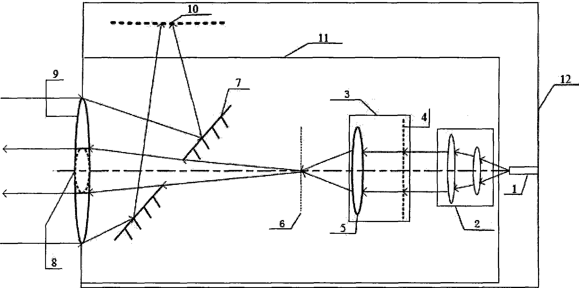
[0024] A non-scanning 3D imaging laser radar optical system 11 based on an APD array is installed in a laser radar system housing 12; f 1 An emission optical unit composed of an emission lens 8, and a focal length f 2 A receiving optical unit composed of a receiving lens 9 and a transmitting-receiving spectroscope 7 is formed; a laser 1 is installed on the inner wall of the tail of the laser radar system housing 12, and the Galileo telescope 2 is installed in front of the laser 1, and the laser beam emitted by the laser 1 is guided into Galileo through an optical fiber. The telescope 2 and the Galileo telescope 2 are equipped with a beam splitter 3 in front, and the beam splitter 3 produces a spot 6, and the beam splitter 3 is equipped with a transmitting-receiving beam splitter 7, adjusting the distance between the transmitting-receiving beam splitter 7 and the spot 6 can select the spot The number of 6, the transmit-receive beamsplitter 7 is located at the spot 6 and the fo...


PUM


Abstract

A non-scanning 3D imaging laser radar optical system based on an APD array is arranged in a shell of a laser radar system. The non-scanning 3D imaging laser radar optical system is composed of a laser, a Galilean telescope, an optical splitter, an emitting optical unit consisting of an emitting-receiving spectroscope and an emitting lens with the focal length of f1 and a receiving optical unit consisting of a receiving lens with the focal length of f2 and the emitting-receiving spectroscope; the inner wall of the tail part of the shell of the laser radar system is provided with the laser, the Galilean telescope is arranged in front of the laser, the optical splitter is arranged in front of the Galilean telescope, the emitting-receiving spectroscope is arranged in front of the optical splitter, is a plane mirror with a hole provided at the center thereof, is positioned between a light spot and the receiving lens with the focal length of f1 and placed at 45 degrees to an optical axis, a port on the shell of the laser radar system is provided with the receiving lens with the focal length of f2, the emitting lens is positioned in the hole at the center of the receiving lens, and the emitting-receiving spectroscope reflects beams at 90 degrees to a detector at a focal plane position of the receiving lens. The optical system has simple structure and high accuracy, and can be applicable to the fields of plotting, navigation and astronautics.

Description

(1) Technical field [0001] The invention relates to a laser radar optical system, in particular to a non-scanning 3D imaging laser radar optical system based on an avalanche photodiode (APD) array, and belongs to the technical field of optical measuring instruments. (2) Background technology [0002] Lidar is one of the rapidly developing high-tech, and it is the product of the combination of traditional radar technology and modern laser technology. The non-scanning 3D imaging lidar based on APD array uses pulsed laser flood illumination and high-sensitivity avalanche photodiode APD focal plane array components to achieve high frame rate single angle-angle-distance three-dimensional imaging. It is a new imaging system lidar. The imaging laser radar system controls the emission of the laser so that the emitted light can cover the entire target at the same time, and then uses a two-dimensional APD array placed on the focal plane of the receiving optical system to receive the ...

Claims


Application Information

Patent Timeline
IPC IPC(8): G01S7/481G01S17/89
Inventor 李丽刘晓波
Owner BEIHANG UNIV
Why Eureka
Try Eureka