Buoy having waveforce self-generating unit and waveforce generating method

A technology of self-generated power and buoys, applied in marine signal devices, buoys, ocean energy power generation, etc., and can solve problems such as unusability

Inactive Publication Date: 2002-12-04
成哲基
View PDF0 Cites 29 Cited by
  • Summary
  • Abstract
  • Description
  • Claims
  • Application Information

AI Technical Summary

Problems solved by technology

However, there must be additional supporting devices such as the ground or lighthouses near this device, so it cannot be used in places without fixed or supporting devices such as the middle of the sea.

Method used


Image

  • Buoy having waveforce self-generating unit and waveforce generating method
  • Buoy having waveforce self-generating unit and waveforce generating method

Examples


Embodiment Construction

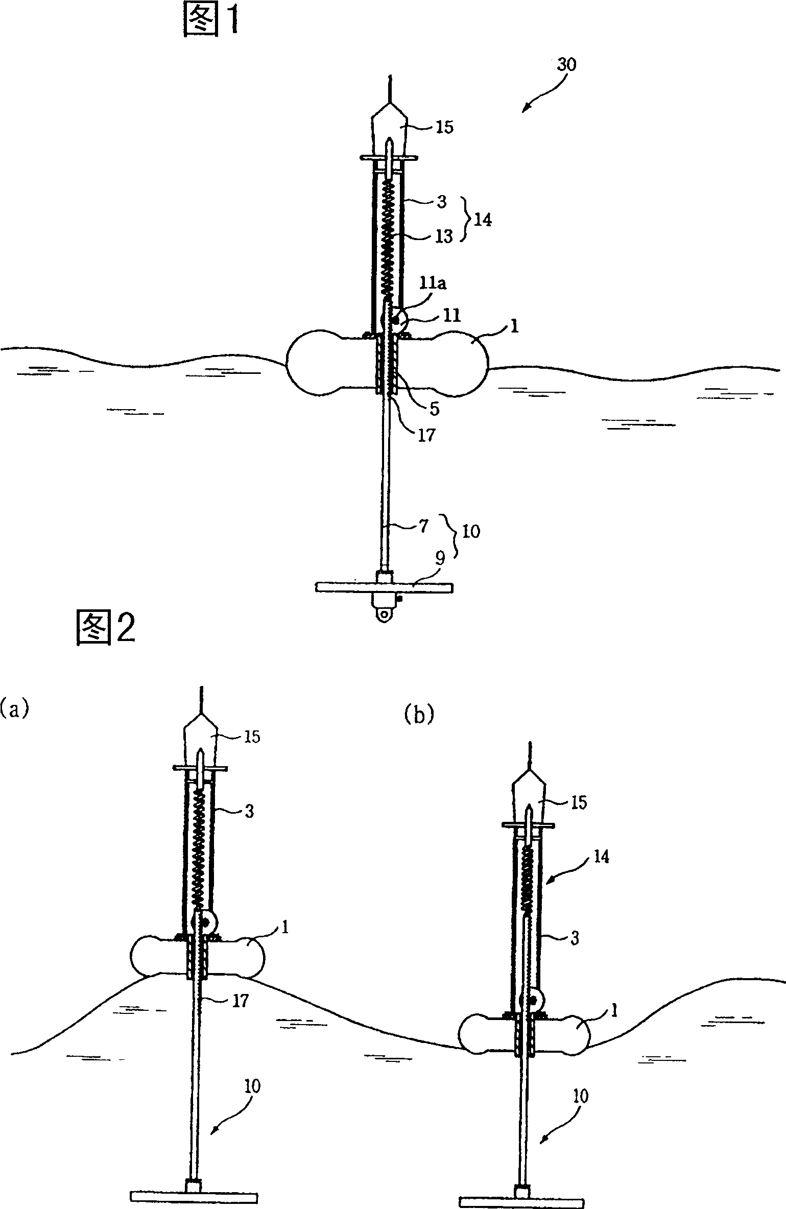
[0014] As shown in FIG. 1 , the self-generating buoy 30 using wave power according to the present invention is composed of a series of components, so that the kinetic energy of waves is converted into electrical energy through a generator.

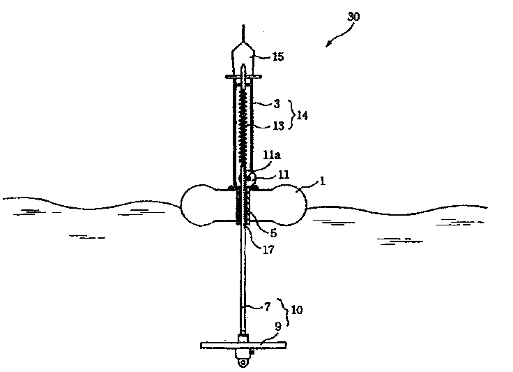
[0015] The buoy includes: a floating body 1 , a lower feeding part 10 , a generator 11 , an upper support 14 and a navigation light 15 . The floating body 1 floats on the sea surface, and its center is provided with a vertical guide sleeve 5 .

[0016] The lower feeding part 10 is composed of a mandrel 7 and a resistance plate 9: the upper part of the mandrel 7 can move relative to the floating body 1 in the vertical direction in the guide sleeve 5; the resistance plate 9 is fixed on the lower end of the mandrel 7 and extends into the sea . When the floating body 1 moves up and down under the action of waves, the resistance plate 9 hinders the movement of the lower feeding part 10, so the two generate relative reciprocating motion along t...


PUM


Abstract

The present invention proposes a buoy with a self-generating device using wave force. The buoy consists of a buoy floating on the sea and a lower feeding part that vertically passes through the guide sleeve at the center of the buoy. Above the floating body, the rack on the upper part of the lower feeding part meshes with the gear on the engine to convert the linear reciprocating motion of the lower feeding part into the rotary motion of the generator, so that the generator generates electricity; the upper support on the floating body is a support It is used for the lower feeding part; a beacon light is set on the buoy, which uses the electric energy generated by the generator to mark the position of the buoy.

Description

technical field [0001] The present invention relates to a buoy with a self-generating device using wave power. The buoy converts the wave power of seawater waves into electric energy and uses the electric energy to emit light. Therefore, it can be used permanently without other power supply devices at sea. Background technique [0002] In order to guide ships to sail safely at sea, several marking devices, such as unmanned lighthouses, light poles, buoys, etc., are usually used to mark safe routes and dangerous areas for navigation. These identification devices generally use dry cells or accumulators as power sources to emit light or electric waves. [0003] However, the traditional buoy must be charged or replaced due to battery consumption. At this time, the ship must be driven to the position where the buoy is set, and the buoy must be hoisted to the ship before proceeding. Therefore, it not only takes a long time and manpower, but also consumes a lot of The cost of batt...

Claims


Application Information

Patent Timeline
Patent Type & Authority Applications(China)
IPC IPC(8): B63B45/00B63B22/00B63B22/18
CPCB63B22/00B63B22/18B63B2209/14Y02E10/30B63B45/00
Inventor 成泰焕
Owner 成哲基
Why Eureka
Try Eureka