Spondylodesis graft

A spinal fusion and graft technology, applied in the field of spinal fusion grafts, can solve the problems of filling adjacent vertebrae, difficulty, trouble, etc., and achieve the effect of increasing bone filling density

Inactive Publication Date: 2002-12-11
李 春泽 +1
View PDF0 Cites 46 Cited by
  • Summary
  • Abstract
  • Description
  • Claims
  • Application Information

AI Technical Summary

Problems solved by technology

However, due to the structural characteristics of existing implants, it is difficult to fill the gap between adjacent vertebrae before surgery
Also, filling the gap through t

Method used


Image

  • Spondylodesis graft
  • Spondylodesis graft
  • Spondylodesis graft

Examples


Example

[0037] The first and second embodiments of the present invention will now be described in detail, and examples of the present invention will be described with reference to the accompanying drawings. In the description of the present invention, the names and item numbers of the same elements are the same, and the same descriptions are omitted.
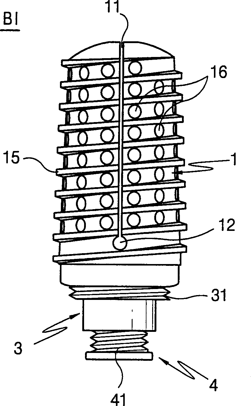
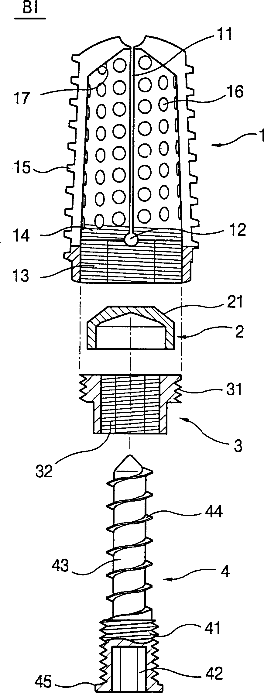
[0038] figure 1 A front view showing the spinal fusion graft of the present invention, figure 2 An exploded cross-sectional view of the spinal fusion graft of the present invention is shown.

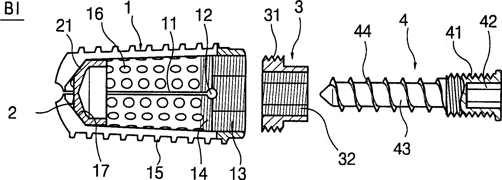
[0039] The main body 1 includes a cylinder with a spherical front end and an open rear end and a cutout portion 11 formed in the main body 1, extending from the front end to the rear end, and cut in at least one direction to enable the front end to expand.

[0040] The cylindrical structure of the body 1 facilitates filling of the body 1 with bone taken from a patient.

[0041] The cutout portion 11 is preferably linear or cross-shaped, so as...


PUM


Abstract

The invention provides a spinal fusion implant, comprising: a cylindrical body with an expandable front end; a cap-shaped extrusion part, which expands the front end of the main body by bearing tension; Can be used as a guide for the engagement of fasteners; fasteners, which engage in closures and push against extrusions. In the present invention, the main body can be inserted into the fusion part during operation, and the front end of the main body can be expanded with extrusions and fasteners, so that the spinal fusion graft can be fixed to fit the anterior and posterior spaces between adjacent vertebrae.

Description

technical field [0001] The present invention relates to a spinal fusion graft for use in spinal fusion surgery. Background technique [0002] In the human body, the spine is connected to the vertebrae through the intervertebral disc to form a "Lasy-S"-shaped curve. The spine is composed of a column and an arch at the rear. The posterior arch includes a spinal canal with a pair of pedicles. The upper or lower costal notch where the arch plate and spinous process extend backward, and the nerve runs through the spinal canal. [0003] In the spine, when the intervertebral discs connecting the vertebrae degenerate and split, or when the joints formed by the kyphosis are damaged and degenerate, the spine will leave its normal position, and the spine will be deformed due to various reasons when external force acts or compresses the nerves that run through the spinal canal And dislocation, just produce pain. [0004] Surgery to fuse the spine, which replaces the ruptured or damage...

Claims


Application Information

Patent Timeline
IPC IPC(8): A61B17/56A61F2/00A61F2/02A61F2/28A61F2/30A61F2/44A61F2/46
CPCA61F2/30744A61F2/442A61F2/4455A61F2/446A61F2/4611A61F2002/2835A61F2002/30217A61F2002/30405A61F2002/3041A61F2002/30507A61F2002/30538A61F2002/30579A61F2002/30593A61F2002/30594A61F2002/30774A61F2002/30777A61F2002/30787A61F2002/30858A61F2002/30873A61F2002/448A61F2002/4627A61F2220/0025A61F2230/0067A61F2250/0006
Inventor 崔吉运
Owner 李 春泽
Why Eureka
Try Eureka