

Static magnetic field control method and magnetic resonance imaging device
A technology of magnetic resonance imaging and static magnetic field, applied in magnetic resonance measurement, measurement device, material analysis through resonance, etc., can solve the problems of permanent magnet polarizer Sp1 being easily affected by temperature change and narrowing of adjustment range, etc.
- Summary
- Abstract
- Description
- Claims
- Application Information
AI Technical Summary
Problems solved by technology
Method used
Image

Examples
no. 1 example
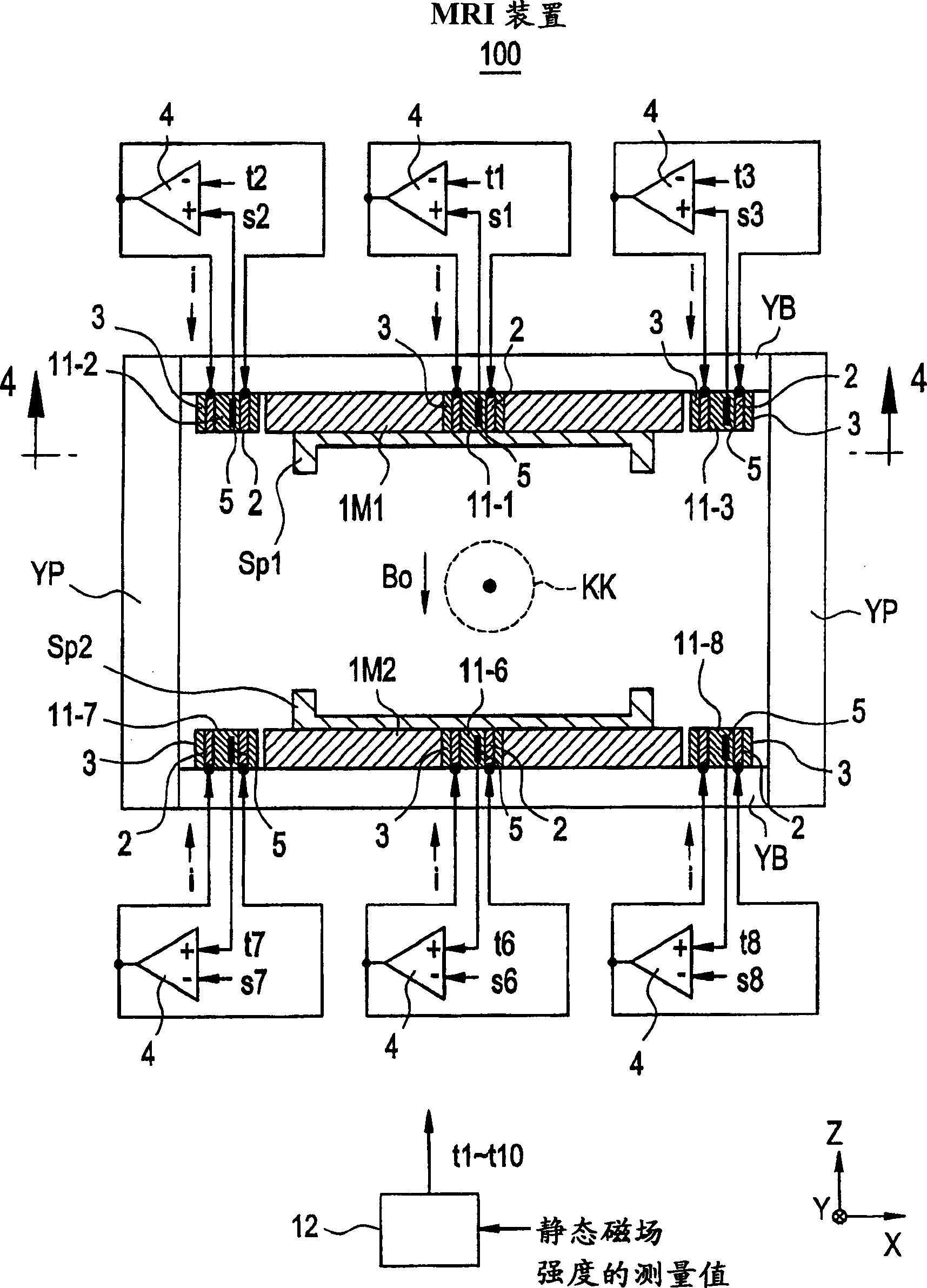
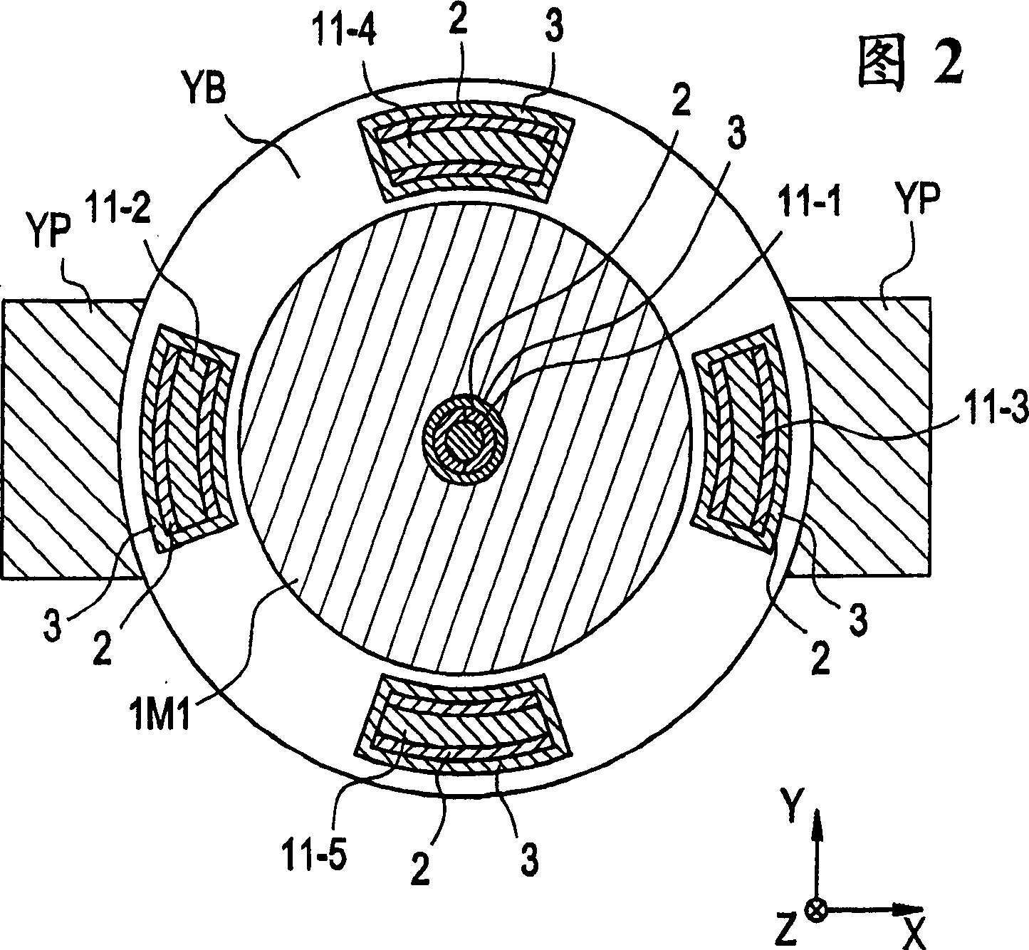
[0060] now refer to figure 1 , which shows a partial sectional view of an MRI apparatus according to a first preferred embodiment of the present invention. Referring also to Figure 2, which shows along the figure 1 The K-K' line sees the past sectional view.
[0061] The MRI apparatus 100 is an open type MRI apparatus that generates a static magnetic field Bo in a vertical direction from permanent magnets, ie, permanent magnets 1M1 and 1M2 installed at opposite positions on the bottom and top.
[0062] On the surfaces of the respective permanent magnets 1M1 and 1M2, deflectors Sp1 and Sp2 are installed, which improve the uniformity of the static magnetic field Bo in the imaging zone KK.
[0063] The permanent magnets 1M1 and 1M2, the deflectors Sp1 and Sp2, the base yoke YB, and the column yoke Yp may constitute a magnetic circuit. Materials for permanent magnets 1M1 and 1M2 may include, for example, neodymium magnetic material (Nd-Fe-B), samarium-cobalt magnetic material...
no. 2 example
[0085] now refer to Figure 6 , which shows a partial cross-sectional view of an MRI apparatus according to a second preferred embodiment of the present invention. Also refer to Figure 7 , which represents along Figure 6 The cross-sectional view seen on the K-K' line.
[0086]In this MRI apparatus 200, the permanent magnet 1M1 and the base yoke YB can be provided with threaded holes at many positions, that is, the static magnetic field adjustment unit installation devices 20-1 to 20-10, which can be freely connected and removed from the Static magnetic field adjustment units 21 - 1 to 21 - 10 selected from a group consisting of a plurality of types of units ( 21α , 21β , 21γ shown in FIG. 8 ).
[0087] Such as Figure 8A As shown, the static magnetic field adjustment unit 21α can be composed of a non-magnetic sleeve 210α and a magnetic core 211α, wherein the sleeve 210α is a hollow cylindrical member, and its shape is a threaded screw, and the magnetic core 211α runs thr...
no. 3 example
[0097] The MRI apparatus according to the third preferred embodiment of the present invention adopts Figure 9 The static magnetic field adjustment unit 31 is shown in place of the static magnetic field adjustment unit 21 (see FIG. 8 ) employed in the second preferred embodiment described above. Specifically, the static magnetic field adjustment unit 31 assembly is adopted, which is screwed into the primary ring 311 of the hollow cylinder form in the center hole of the final ring 310 in the form of a hollow cylinder, and screwed into the solid ring 311 in the center hole of the primary ring 311. A core 312 in the form of a cylinder is assembled.
[0098] As shown in FIGS. 10 ( A1 ) and ( B1 ), either one of the final ring 310A of magnetic material or the final ring 310B of nonmagnetic material will be selected as the final ring 310 .
[0099] As shown in FIGS. 10(A2) and (B2), either one of the primary ring 311A of magnetic material or the primary ring 311B of non-magnetic ...
PUM
 Abstract
Description
Claims
Application Information