Blower

A blower and fan technology, applied in mechanical equipment, machines/engines, liquid fuel engines, etc., can solve problems such as increased air flow resistance, increased noise, and low blowing efficiency

Inactive Publication Date: 2003-03-19
LG ELECTRONICS INC
View PDF0 Cites 10 Cited by
  • Summary
  • Abstract
  • Description
  • Claims
  • Application Information

AI Technical Summary

Problems solved by technology

[0008] However, according to the blower of the prior art, since the impeller 1 called a Sirocco fan is installed inside the volute 2, there is a limit to increasing the blowing volume, and the cut-off portion 3 formed on the volute is limited. Tilt angle θ 1 An angle of 50° or less is formed from the impeller shaft 11, and as a result, the air flow resistance through the funnel portion 2b increases, resulting in low blowing efficiency and increased noise.

Method used


Image

  • Blower
  • Blower
  • Blower

Examples


Embodiment Construction

[0021] An embodiment of the blower according to the present invention will be described in detail below with reference to the accompanying drawings.

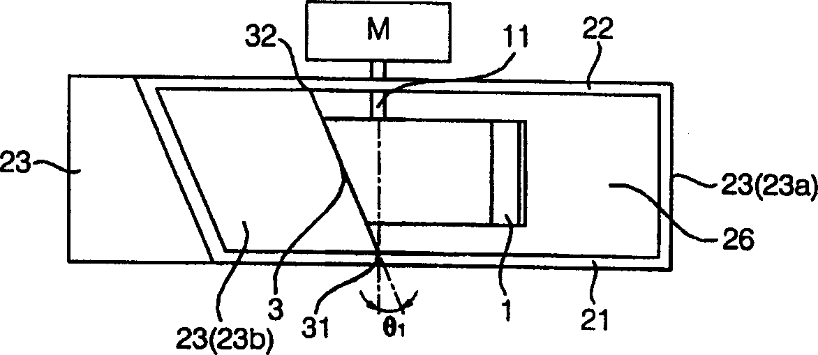
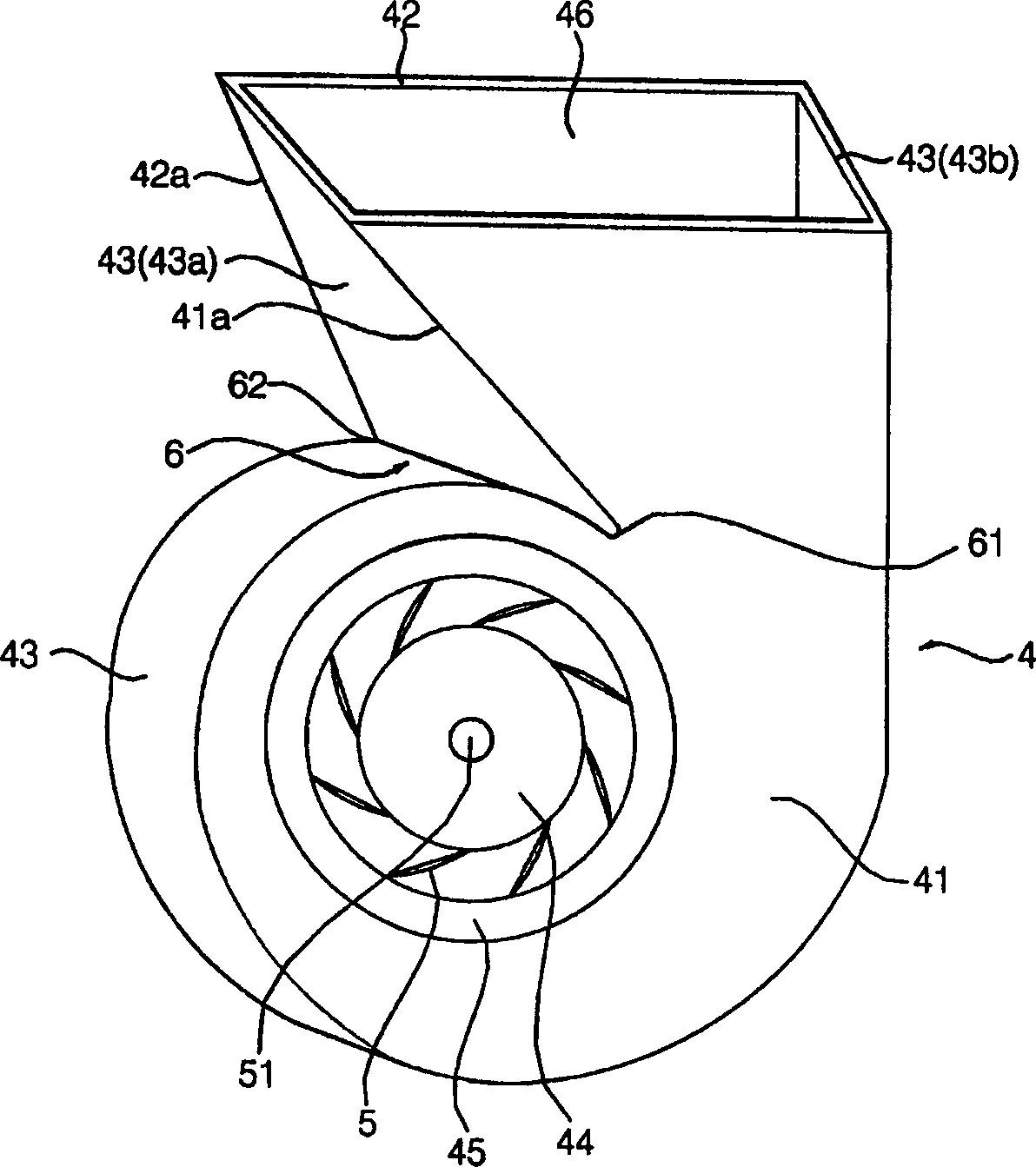
[0022] image 3 is a perspective view of a blower according to the invention, Figure 4 is a partially cut-away front view of a blower according to the invention, Figure 5 yes Figure 4 floor plan.

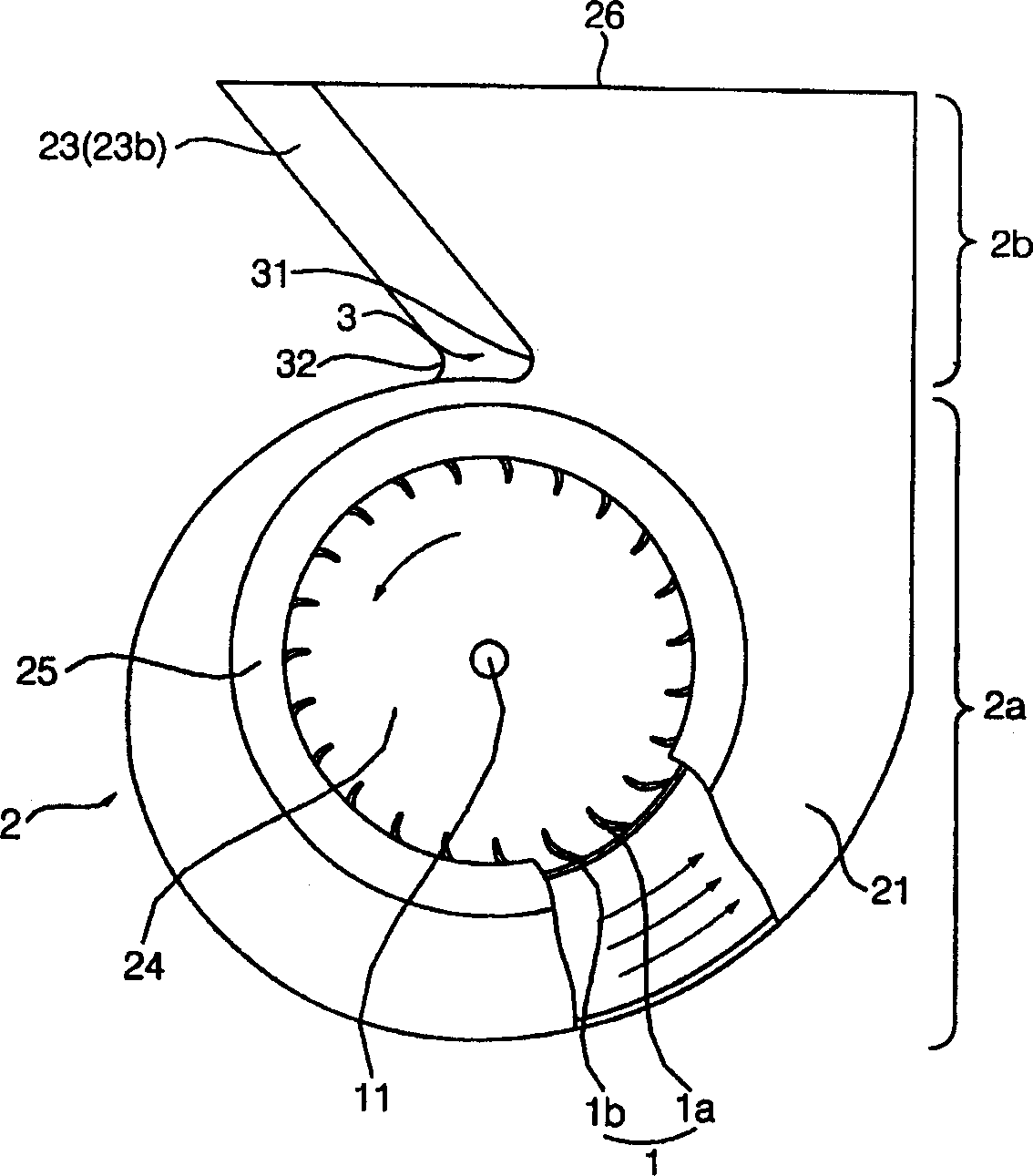
[0023] Such as Figures 3 to 5 As shown, the blower of the present invention is composed of a volute 4 and a turbofan 5 arranged in the volute.

[0024] Described volute 4 comprises: main body portion 4a, and it forms garden-shaped suction port 44, and forms bell mouth 45 at the outer peripheral edge of described suction port 44, and turbo fan 5 is arranged inside and guides the air sucked by described suction port 44 The direction of rotation of the turbofan 5; the funnel part 4b, which forms an exhaust port 46 at the end, extends from the main body part 4a to the exhaust port 46 side so that the discharge area gradually expa...


PUM


Abstract

A blower having a turbo fan is installed in a scroll housing with a cutoff. The cutoff has an inclination angle of approximately 50 to 80 DEG , so that it is possible to draw in an increased amount of air while reducing the flow resistance of air. Accordingly, blowing efficiency is improved while simultaneously reducing the generation of noise and vibration.

Description

technical field [0001] The present invention relates to a blower installed in household appliances such as air conditioners and cleaning machines to inhale and discharge air, in particular to setting a turbo fan in a volute and increasing the inclination angle of the cut-off part of the volute so as to improve the blowing performance , to reduce the noise of the blower. Background technique [0002] Blowers according to the prior art such as figure 1 and figure 2 As shown, it generally consists of an impeller 1 called a Sirocco fan and a volute 2 that guides the air sucked in by the impeller 1 to be discharged at an exhaust port 26 . [0003] The impeller 1 is composed of a plurality of blades 1a supported by ribs 1b. Since the shaft 11 of the impeller 1 is connected to the driving part of the motor M, while the impeller 1 rotates, the air is sucked into the volute 2 through the suction port 24 formed in front of the volute 2 and guided by the bell...

Claims


Application Information

Patent Timeline
Patent Type & Authority Applications(China)
IPC IPC(8): F04D29/44F04D29/42F04D29/66
CPCF04D29/422F04D29/4226F04D29/44
Inventor 金承天朴营民朴钟汉李浚世崔圣吾
Owner LG ELECTRONICS INC
Why Eureka
Try Eureka