Self-balanced coal continuous gasification furnace

A self-balancing, gasification furnace technology, applied in the manufacture of combustible gas, petroleum industry, etc., can solve the problems of inability to effectively adjust the heat balance effect, and achieve continuous and stable operation, streamlined structure, and simplified operating procedures Effect

Inactive Publication Date: 2003-03-26
刘工勤
View PDF2 Cites 5 Cited by
  • Summary
  • Abstract
  • Description
  • Claims
  • Application Information

AI Technical Summary

Problems solved by technology

It cannot or cannot effectively play the role of automatically adjusting the heat balance effect

Method used


Image

  • Self-balanced coal continuous gasification furnace
  • Self-balanced coal continuous gasification furnace
  • Self-balanced coal continuous gasification furnace

Examples


Embodiment Construction

[0011] The embodiments of the present invention will be described in detail below in conjunction with the accompanying drawings. These embodiments are used to illustrate the present invention, but not to limit the present invention.

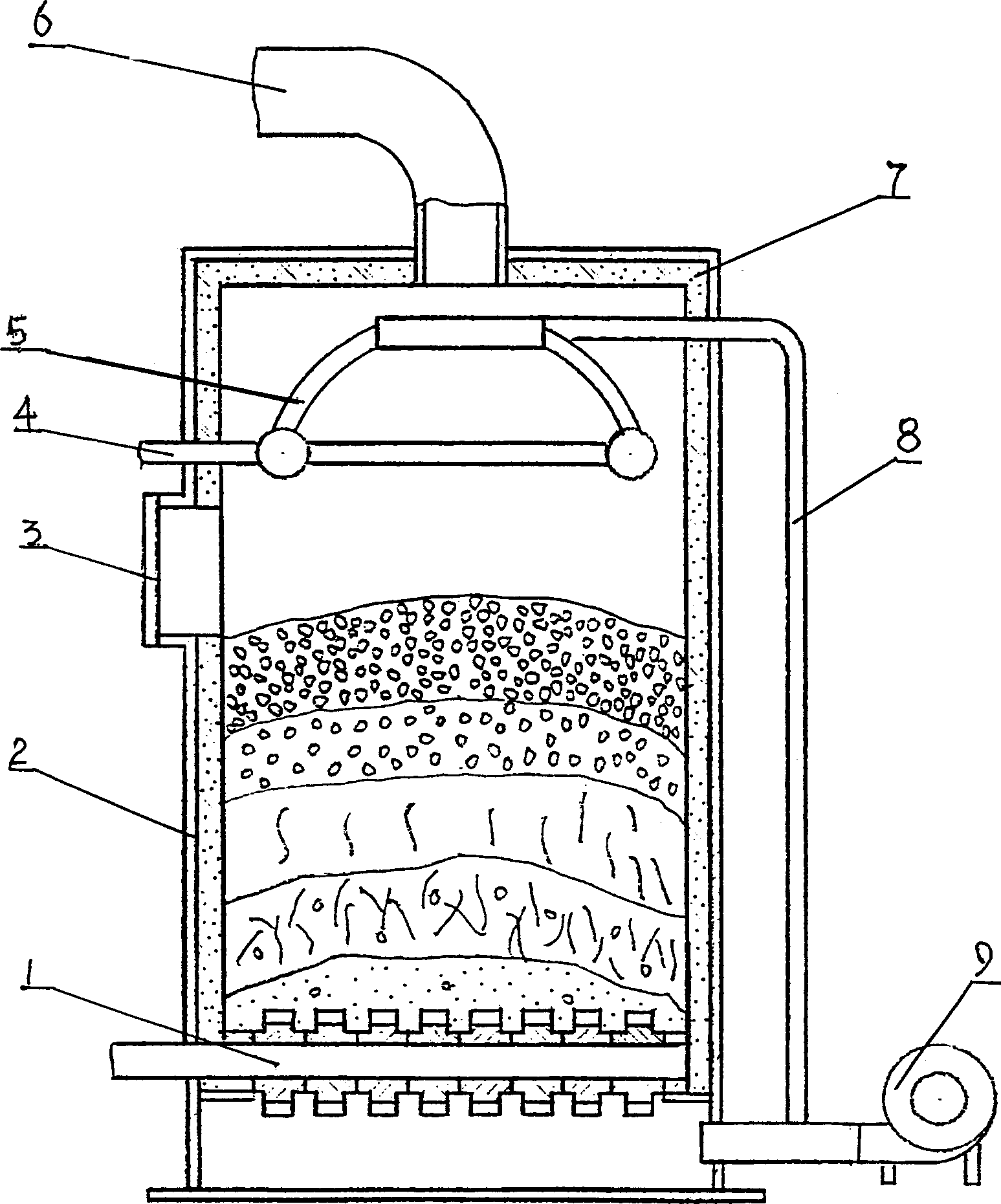
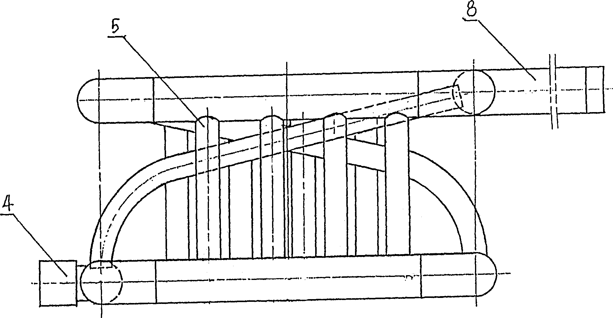
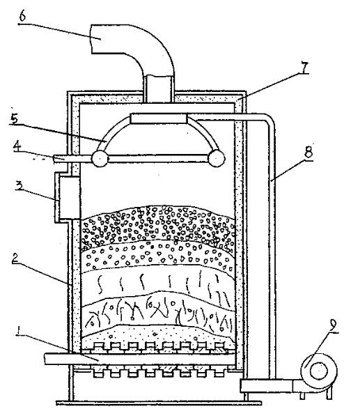
[0012] The self-balancing continuous coal gasifier includes a grate (1), a furnace body (2), and a gas delivery pipe (6). A steam generator (5) is arranged on the upper part of the furnace cavity corresponding to the fuel preparation layer, and the steam is generated The water inlet (4) of the device (5) is connected to the cold water source, and the steam outlet pipe (8) of the steam generator (5) is connected to the air outlet pipe of the blower (9), and the air outlet pipe of the blower (9) is passed into the furnace body Below the chamber grate (1). The steam generator (5) is a hollow water jacket placed on the upper part of the inner cavity of the furnace corresponding to the fuel preparation layer. The steam generator (5) can also be unifo...


PUM


Abstract

A kind of self-balance coal continuous gasification stove includes grate, furnace, gas tube, there is a steam generator in the internal top of furnace body corresponding to the fuel preparing layer, the water entrance of steam generator connects with cool water source, the steam exit connects with the wind exit of fan, the wind exit tube extends into furnace body under the grate. The steam generator is hollow set in the lumen top of furnace body above the fuel preparing layer. It also can be even interflowing tubes and set in the same position.

Description

technical field [0001] The invention belongs to coal burning equipment, in particular to a self-balancing coal continuous gasifier. Background technique [0002] Solid fuels such as coal and coke can be converted into combustible gas through chemical reaction with gasification agent in coal gasifier under certain reaction conditions (temperature, pressure) to obtain gasified gas. The thermal effect balance in the gasification process is a necessary condition for the normal and stable operation of the coal gasifier. In the known technology, the chemical reaction conditions in the coal gasification process of the coal gasifier are regulated by complicated control devices in order to obtain an ideal heat balance reaction. In terms of water vapor production, for example, Chinese patents No. 00213331.8 and No. 00209032.5 adopt the structure of a water jacket with a wall or a secondary air pipe, which is mainly for the purpose of utilizing and absorbing waste heat. It cannot or ...

Claims


Application Information

Patent Timeline
IPC IPC(8): C10J3/00
Inventor 刘工勤
Owner 刘工勤
Why Eureka
Try Eureka