
Laser inter-satellite link terminal autonomous relay method and system for flying-around formation

A technology of inter-satellite links and terminals, which is applied to aircraft, artificial satellites, space navigation equipment, etc., can solve problems that do not involve laser terminal relay, etc., to ensure link continuity and stability, simple implementation, and reduced Effects of Ground Intervention

Active Publication Date: 2020-11-13
SHANGHAI SATELLITE ENG INST
View PDF6 Cites 0 Cited by
  • Summary
  • Abstract
  • Description
  • Claims
  • Application Information

AI Technical Summary

Problems solved by technology

[0003] Research papers on related technologies, "A Review of Laser Intersatellite Link Rapid Acquisition Technology" (Lin Yiming et al., Spacecraft Engineering, Vol. 27, No. 1), introduced pointing error modeling of laser intersatellite link terminals, The development status at home and abroad in the four aspects of error on-orbit calibration, laser inter-satellite link scanning capture parameter optimization, and link interruption recovery and recapture, but it does not involve the problem of laser terminal relay in the process of satellite laser communication in formation networking
[0004] Patent document CN102230969B (application number 201110069351.4) discloses a long-term autonomous maintenance method for inter-satellite links of satellite constellations. The long-term prediction of the inter-satellite relative position is carried out by using the orbit improvement and prediction model of the analytical orbit on the satellite, mainly involving Inter-satellite relative position prediction, does not involve laser terminal autonomous relay method

Method used


Image

  • Laser inter-satellite link terminal autonomous relay method and system for flying-around formation
  • Laser inter-satellite link terminal autonomous relay method and system for flying-around formation
  • Laser inter-satellite link terminal autonomous relay method and system for flying-around formation

Examples


Embodiment

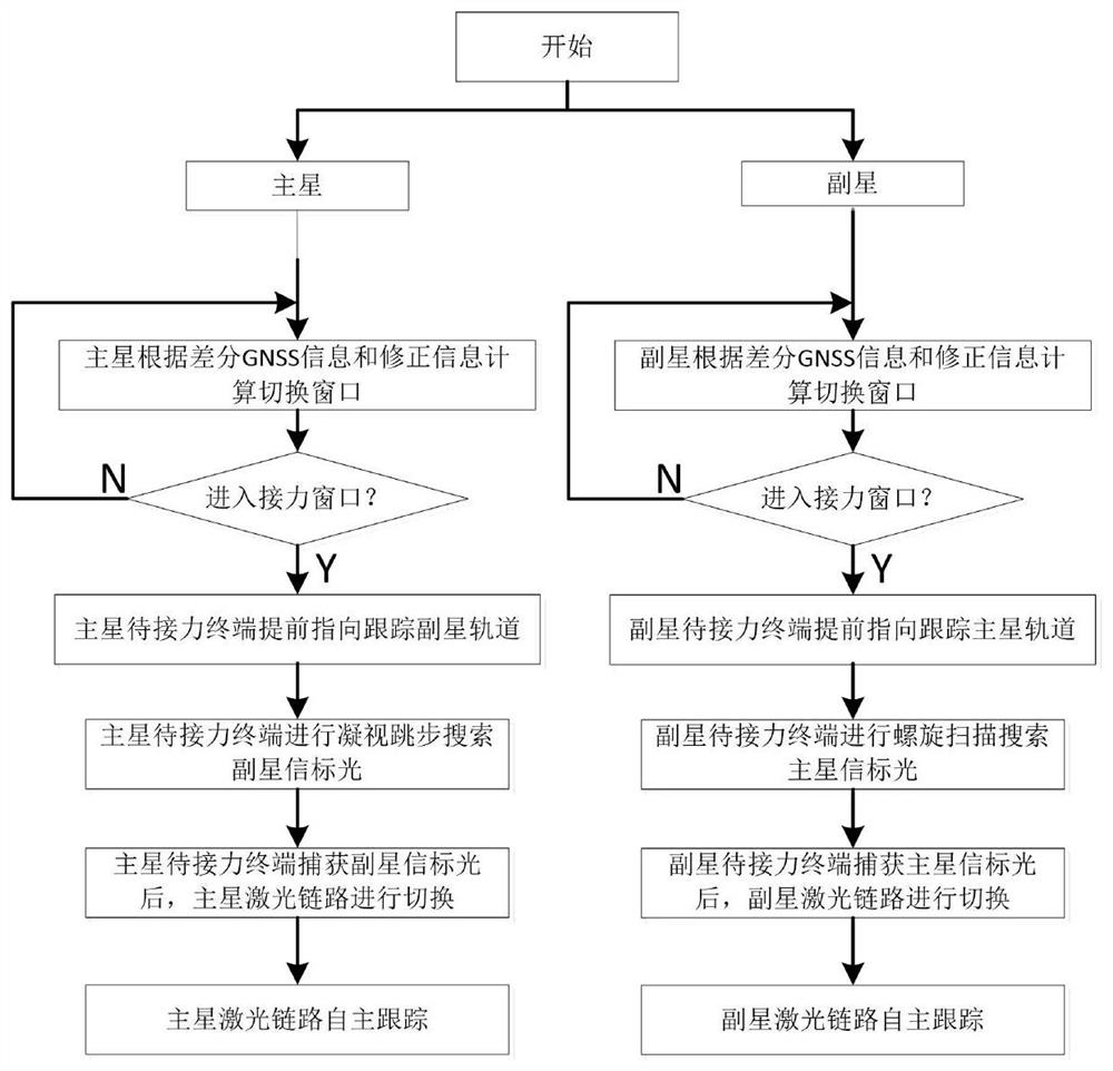
[0039] Such as figure 1 , according to the autonomous relay method of the laser inter-satellite link terminal for flying around the formation provided by the present invention, the flying around formation configuration refers to the formation configuration in which the secondary star performs 360-degree orbiting flight relative to the main star, and the terminal refers to A laser communication terminal, comprising the following steps:

[0040] Step 1: The primary star obtains its own and secondary star GNSS information, and the secondary star obtains its own and primary star GNSS information, and the GNSS information includes position, speed and time information;

[0041] Step 2: The primary star recursively calculates the line-of-sight vector of the secondary star in the main star body coordinate system in real time based on the secondary star and its own GNSS information. The line-of-sight vector of the body coordinate system;

[0042] Step 3: According to the line-of-sigh...


PUM


Abstract

The invention provides a laser inter-satellite link terminal autonomous relay method and system for flying-around formation. The method comprises the steps that: step 1, a primary satellite and a secondary satellite obtain GNSS information of the primary satellite and GNSS information of the secondary satellite respectively; step 2, sight vectors of the primary and secondary satellites in oppositeside body coordinate systems are recursively calculated in real time according to the GNSS information by the primary and secondary satellites; step 3, the main satellite selects a relay terminal andcalculates a relay window according to the sight vector of the auxiliary satellite in the main satellite body coordinate system in combination with the on-satellite layout of a main satellite laser terminal; the secondary satellite performs relay terminal selection and relay window calculation according to the sight vector of the primary satellite in the secondary satellite body coordinate system; and step 4, to-be-relayed terminals of the primary satellite and the secondary satellite respectively search, capture and track the beacon light of the target terminal so as to realize switching andautonomous tracking of the laser link. The method is easy to implement, the inter-satellite laser link operates autonomously, continuously and stably in the formation operation process, ground intervention is reduced, and link continuity and stability are guaranteed to the maximum extent.

Description

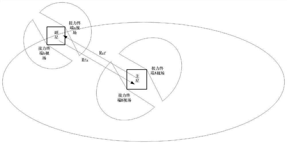
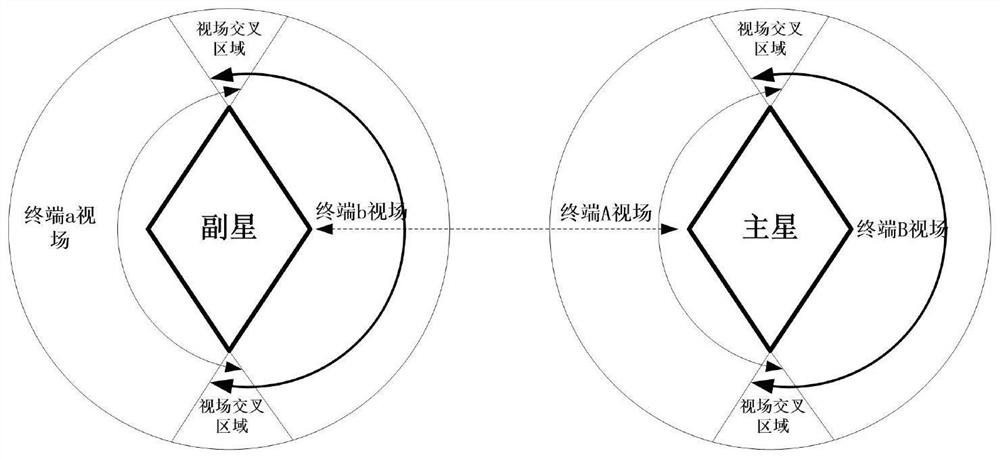
technical field [0001] The present invention relates to the technical field of inter-satellite laser communication, in particular to a method and system for autonomous relaying of laser inter-satellite link terminals used for fly-around formations. In particular, it relates to an autonomous relay method for laser inter-satellite link laser terminals adapted to fly-around formation configurations. Background technique [0002] In order to reliably and stably realize continuous inter-satellite laser communication in a multi-satellite formation satellite system with orbiting configuration, so as to ensure and improve the mission efficiency of the satellite system, it is necessary to solve the problem of autonomous relay of the laser communication terminal, that is, the secondary satellite orbits the main satellite for 360 degrees. In the process of orbiting at a high degree, the laser communication terminals of the primary star and the secondary star are required to be able to ...

Claims


Application Information

Patent Timeline
Patent Type & Authority Applications(China)
IPC IPC(8): B64G1/10B64G1/22
CPCB64G1/1007B64G1/22
Inventor 茹海忠陈占胜成飞曹岸杰凌惠祥杨燕袁双
Owner SHANGHAI SATELLITE ENG INST
Learn More