
Pump device and method for generating adjustable constant fluid volume flow and its application

A volume flow, pump device technology, applied to the components of pumping devices for elastic fluids, pumps for special fluids, pump devices, etc., can solve problems such as leakage and achieve easy-to-implement effects

Inactive Publication Date: 2003-04-02
LEVITRONIX TECH
View PDF2 Cites 5 Cited by
  • Summary
  • Abstract
  • Description
  • Claims
  • Application Information

AI Technical Summary

Problems solved by technology

For example, leakage due to the presence of wear particles, such as along the piston of a piston pump, when piston rings and / or barrel walls are damaged

Method used


Image

  • Pump device and method for generating adjustable constant fluid volume flow and its application
  • Pump device and method for generating adjustable constant fluid volume flow and its application
  • Pump device and method for generating adjustable constant fluid volume flow and its application

Examples


Embodiment Construction

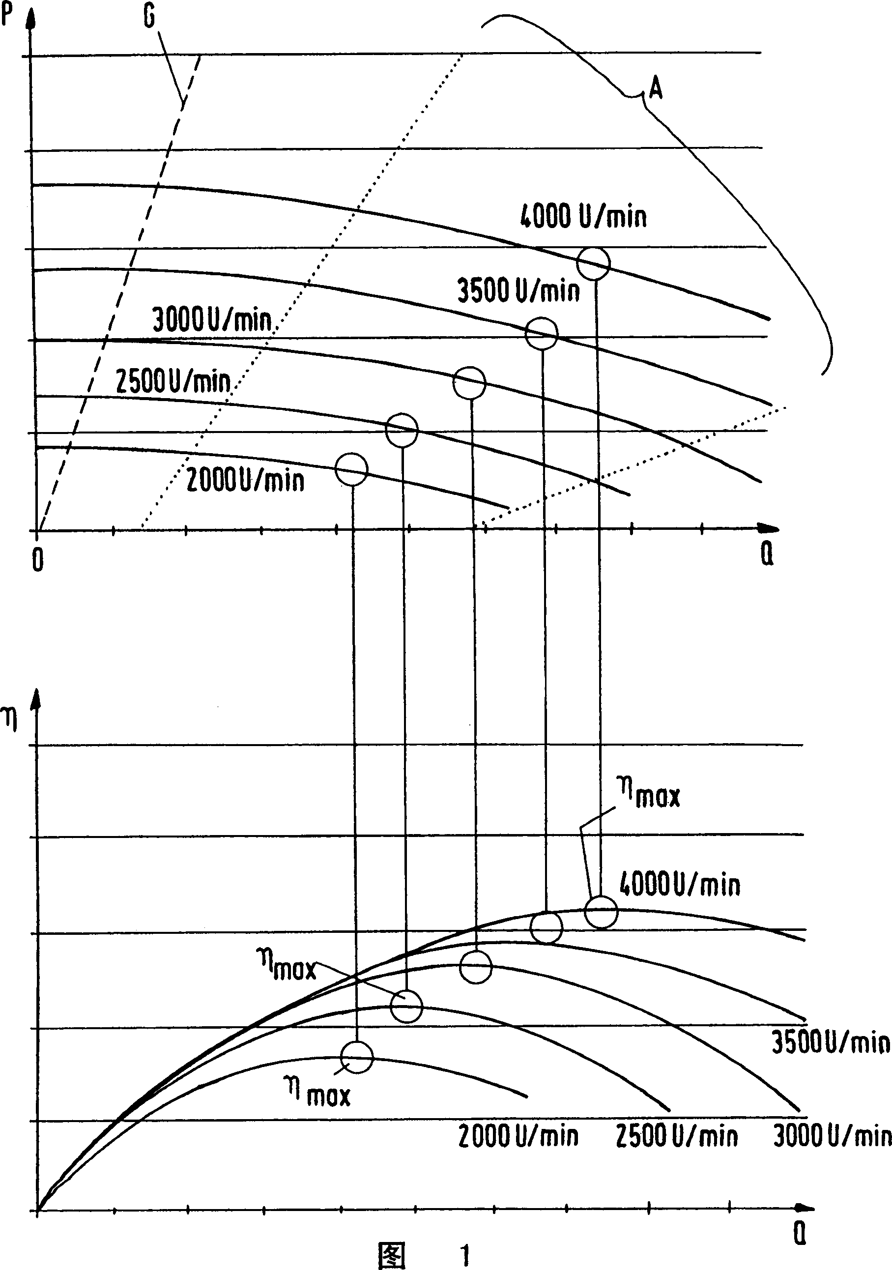
[0024] A method for producing an adjustable and approximately constant volumetric flow of a fluid is characterized in particular by the use of a rotary pump which operates at an efficiency of less than half the maximum efficiency of the rotary pump. Preferably, the efficiency is up to twenty percent of the maximum efficiency.

[0025] Figure 4 An embodiment configuration implementing the method of the invention is shown. Here, the rotary pump 1 is designed as a centrifugal pump with a rotor 10 whose inlet is connected to a reservoir 2 in which the fluid 5 to be conveyed is located. The outlet of the rotary pump 1 is connected via a fluid connection 4 to a doser 6 with a nozzle 61 .

[0026] A particularly important practical application of the method of the invention as part of a chemical mechanical polishing (CMP) process in the semiconductor industry is mentioned below by way of example. In these processes, a suspension (ie slurry) having very fine solid particles in the...


PUM


Abstract

The invention provides a method and a pump apparatus provided for the generation of an adjustable, substantially constant volume flow of a fluid by means of a pump apparatus, wherein the fluid (5) is forwarded by the pump apparatus (1) from a reservoir (2) into a flow connection (4). A rotary pump (1) is used as the pump apparatus and the rotary pump (1) is operated at an efficiency which is less than half the maximum efficiency (eta max) of the rotary pump (1).

Description

technical field [0001] The invention relates to a method and a pump device for producing an adjustable and substantially constant volumetric flow of a fluid as described in the preambles of the independent claims of the corresponding class, and to the use of this method. Background technique [0002] In many industrial processes and a large number of process operations it is necessary to deliver fluids in a metered manner, ie a fluid with an approximately constant volume flow should be delivered in such a way that the quantity of fluid delivered per unit of time is constant. An example that may be given here is the chemical mechanical polishing (CMP) process as applied in the semiconductor industry. In such a process, a suspension, usually called a slurry, generally composed of very fine solid particles and a liquid, is applied to a rotating wafer where it is used to polish or grind very fine semiconductor structures. In this respect, it is necessary to apply the suspension...

Claims


Application Information

Patent Timeline
Patent Type & Authority Applications(China)
IPC IPC(8): B24B37/00A61M1/10F04D7/04F04D13/16F04D15/00F04D29/046G01N11/14H01L21/304H02K7/09H02K21/12
CPCF04D15/0066H02K21/12F04D15/0022G01N2011/147A61M1/101A61M2001/1015G01N11/14H02K7/09F04D7/04H02K41/031
Inventor R·舍布
Owner LEVITRONIX TECH
Learn More