Supercharge Your Innovation With Domain-Expert AI Agents!

Axial vibration preventing mechanism and brushless motor having it

An axial vibration and configuration technology, which is applied to synchronous motors, electromechanical devices, and mechanical equipment with static armatures and rotating magnets. question

Inactive Publication Date: 2003-04-02
TOKYO PARTS IND CO LTD
View PDF0 Cites 5 Cited by
  • Summary
  • Abstract
  • Description
  • Claims
  • Application Information

AI Technical Summary

Problems solved by technology

[0007] However, the above-mentioned method of shifting the center of the magnetic field usually cannot obtain the expected pushing force, and when the shift is large, the magnetic force of the magnet will be reduced to deteriorate its characteristics, the leakage of the magnetic flux line will increase, and strong magnetic field noise will occur. , there is a problem of affecting the device body

Method used


Image

  • Axial vibration preventing mechanism and brushless motor having it
  • Axial vibration preventing mechanism and brushless motor having it
  • Axial vibration preventing mechanism and brushless motor having it

Examples


Embodiment Construction

[0028] Hereinafter, embodiments of the present invention will be described with reference to the drawings.

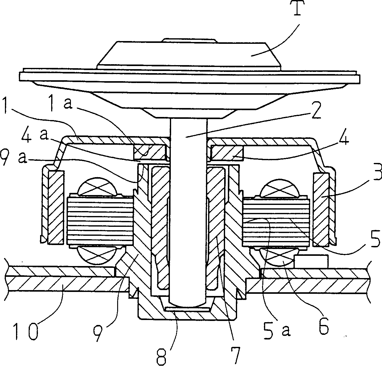
[0029] figure 1 In the center part of the rotor yoke 1 formed in an inverted cup shape, the shaft 2 is fastened; on the inner peripheral side of the yoke 1, the driving magnet 3 is fastened, and the shaft 2 is inserted into the rotor yoke 1. The ring-shaped generation pre-pressure magnet 4 is fastened on the peripheral surface. On the other hand, an armature coil 6 is wound around the stator core 5, and a bearing bracket 9 made of a magnetic material is inserted in the central annular portion 5a of the stator core 5, and a radial bearing 7 and a thrust bearing 8 are held inside it. ; The bearing bracket 9 is fastened on the stator base 10 .

[0030] The bottom 4a of the magnet 4 for preload generation and the opening 9a of the bearing bracket 9 are arranged to have a gap close to each other so as not to affect the rotation, and the turntable T on which the information...


PUM


Abstract

This invention can reliably prevent axial vibration by biasing the rotor toward a thrust bearing through a simple structure so that the rotor is settled on the thrust bearing. A rotor R having a driving magnet 3 and a rotor yoke 2 with the driving magnet installed inside, a shaft 2 installed in the center of the yoke, and a bearing housing 9 having a radial bearing that rotatably supports the shaft and a thrust bearing are provided. A pre-load generating magnet 4 is placed around the shaft as a means of biasing the rotor toward the thrust so that the base end of the shaft sits on and is supported by the thrust bearing. A bearing housing 9 composed of a magnetic substance faces the pre-load generating magnet 4 with a gap in-between.

Description

technical field [0001] The present invention relates to an axial vibration prevention mechanism of a spindle motor capable of rotationally driving an information recording magnetic disk preferably, and a brushless motor provided with the mechanism. Background technique [0002] In recent years, information recording disks such as CD-ROMs and DVDs have been required to be rotationally driven at high speed, and high-speed rotation of a spindle motor for rotationally driving the disks has been desired. In this motor, a bearing bracket is fixed at the central part of the stator base forming the stator, and a thrust bearing is arranged inside the cylinder of the bearing bracket, which pivotally supports the radial bearing and the base end of the shaft; The shaft is inserted through the central part of the rotor yoke, and the above-mentioned radial bearing is used to support the shaft in a rotatable manner. Furthermore, a stator core is fastened to the cylindrical outer periphera...

Claims


Application Information

Patent Timeline
IPC IPC(8): F16C32/04F16C39/06G11B19/20H02K5/16H02K5/167H02K5/24H02K7/08H02K7/09H02K21/22H02K29/00
CPCF16C25/045H02K5/16H02K7/09
Inventor 土屋昌久
Owner TOKYO PARTS IND CO LTD
Features
  • R&D
  • Intellectual Property
  • Life Sciences
  • Materials
  • Tech Scout
  • Unparalleled Data Quality
  • Higher Quality Content
  • 60% Fewer Hallucinations
Learn More