Charging rate regulating circuit for battery group

A technology for adjusting the circuit and charging rate, applied in the direction of charging/discharging of secondary batteries, battery circuit devices, charge equalization circuits, etc. Effect

Inactive Publication Date: 2003-04-09
SANYO ELECTRIC CO LTD
View PDF0 Cites 16 Cited by
  • Summary
  • Abstract
  • Description
  • Claims
  • Application Information

AI Technical Summary

Problems solved by technology

[0009] However, in the prior charging rate adjustment circuit (6), if Figure 9 As shown, it is necessary to dispose the discharge circuit (63) for each battery module (70) constituting the battery pack, therefore, the scale of the circuit becomes large, and there are problems of reduced reliability of circuit operation and increased cost.

Method used


Image

  • Charging rate regulating circuit for battery group
  • Charging rate regulating circuit for battery group
  • Charging rate regulating circuit for battery group

Examples


no. 1 Embodiment

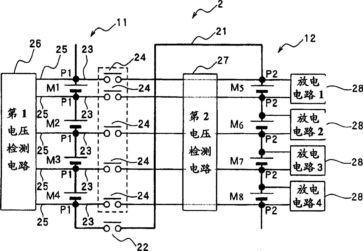
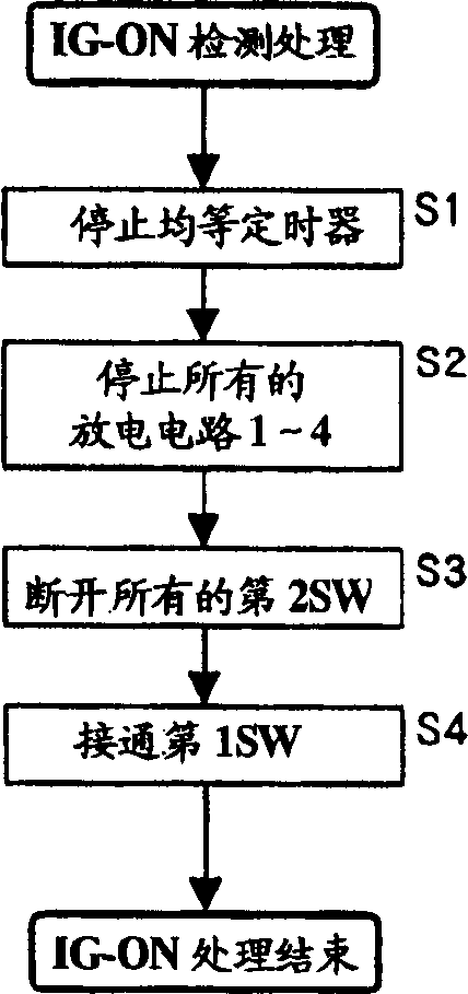
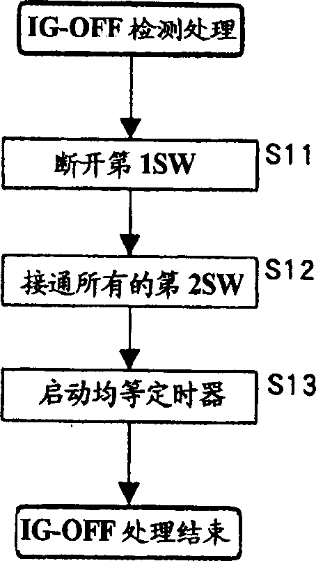
[0057] figure 1 The configuration of the charge rate adjustment circuit (2) for a battery pack composed of two battery blocks (11) (12) is shown. In the circuit (2), the first battery block (11) and the second battery block (12) are respectively constructed by using one or more rechargeable batteries as battery modules and connecting four battery modules in series. A series wire (21) is led out from the negative pole of the first battery block (11), and the front end of the series wire (21) is connected to the positive pole of the second battery block (12). The first switch (22) is inserted into the series line (21), and the two battery blocks (11) (12) are connected in series by the first switch (22). On the other hand, the first switch (22) is turned off. Open to cut off the connection of two battery blocks (11) (12).

[0058] Five parallel connection points P1 are set at the connection points between the two ends of the first battery block (11) and the battery modules M1...

no. 2 Embodiment

[0086] The charging rate adjustment circuit (3) of the present embodiment configures a resistor in the charging rate adjustment circuit of the first embodiment, such as Figure 5 As shown, five parallel wires (23) are respectively inserted into resistors (30). For example, when the maximum potential difference generated between the two battery modules corresponding to the first and second battery blocks (11) (12) is 1.2V, and the allowable current value of the second switch (24) is 2A, the resistance (30 ) can be set to a resistance value of 0.6Ω.

[0087] In the charging rate adjustment circuit (3) of the present embodiment, even if there is a maximum difference between the charging rates of the two battery modules corresponding to the first and second battery blocks (11) (12), when all the second When the switch (24) is set to be turned on, the second switch (24) will not flow a larger current than the allowable current value, which can prevent the second switch (24) from b...

no. 3 Embodiment

[0101] Figure 7 The configuration of the charging rate adjustment circuit (4) of this embodiment is shown. The charging rate adjustment circuit (4) is a circuit for a battery pack composed of three battery blocks (11) (12) (13), from the first battery block (11) and the second battery block (12) The negative poles lead out series wires (41) respectively, and the front end of the series wires (41) drawn out from the negative pole of the first battery block (11) is connected to the positive pole of the second battery block (12). On the other hand, the front end of the series wire (41) drawn from the negative electrode of the second battery block (12) is connected to the positive electrode of the third battery block (13). Insert the first switch (42) in each series line (41), and connect the first to third battery blocks (11) (12) (13) in series by turning on the two first switches (42) (42) , On the other hand, the connection of the first to third battery blocks (11) (12) (13...


PUM


Abstract

The invention provides a charging rate adjusting circuit 2 which comprises a serial line 21 for connecting a plurality of cell blocks 11, 12, a switch 22 interposed on the line 21, a plurality of parallel lines 23 for connecting a plurality of parallel connecting points each corresponding to in the cell blocks 11, 12, switches 24 each interposed on each of the lines 23, discharge circuits 28 connected to a opposite electrodes of each of the cell modules, a voltage measuring circuit 26 for detecting voltage across each of the cell modules, and a control circuit. The control circuit, in usual operation, sets on the switch 22 and sets off all the switches 24, while, in adjustment, the circuit sets off the switch 22 and sets on all the switches 24, and sets on the discharge operation of the circuit 28 based on detection result of the circuit 26.

Description

technical field [0001] The present invention relates to a circuit for adjusting the charge rate of a plurality of battery modules constituting a high-voltage battery pack used as a power source for a drive motor of an electric vehicle such as a hybrid vehicle. Background technique [0002] Conventionally, in electric vehicles such as hybrid vehicles, a battery pack in which a plurality of rechargeable batteries are connected in series is mounted as a power source for driving a motor. In such a battery pack, usually, a high voltage of 200 to 300V must be generated, so for example, for a lithium rechargeable battery with an output of about 3.6V per cell, 60 to 80 cells are connected in series to form a battery pack. The output of each battery is about 1.2V NiMH rechargeable battery, and about 200 batteries are connected in series to form a battery pack. [0003] In such a battery pack, it is desirable that all rechargeable cells have the same state of charge. For example, wh...

Claims


Application Information

Patent Timeline
Patent Type & Authority Applications(China)
IPC IPC(8): B60L11/18H01M10/44H02J7/00H02J7/02
CPCH02J7/0024Y02T10/7055H02J7/0016Y02T10/70
Inventor 古川公彦
Owner SANYO ELECTRIC CO LTD
Why Eureka
Try Eureka