

Equipment for processing paper-like material
A material processing and paper technology, applied in the field of 03], can solve the problems of position displacement and expansion
- Summary
- Abstract
- Description
- Claims
- Application Information
AI Technical Summary
Problems solved by technology
Method used
Image

Examples
no. 1 example
[0094] Refer below Figure 4 with Figure 7 as well as Figure 8 The flowchart shown in is an explanation of the correcting operation by the first correcting mechanism 32 of the attitude correcting device 11 in the above structure.
[0095] Assume now that there is a banknote P delivered to the first correction mechanism through the delivery path 7 Figure 7 The horizontal deflection angle α and shift ΔS shown in solid line.
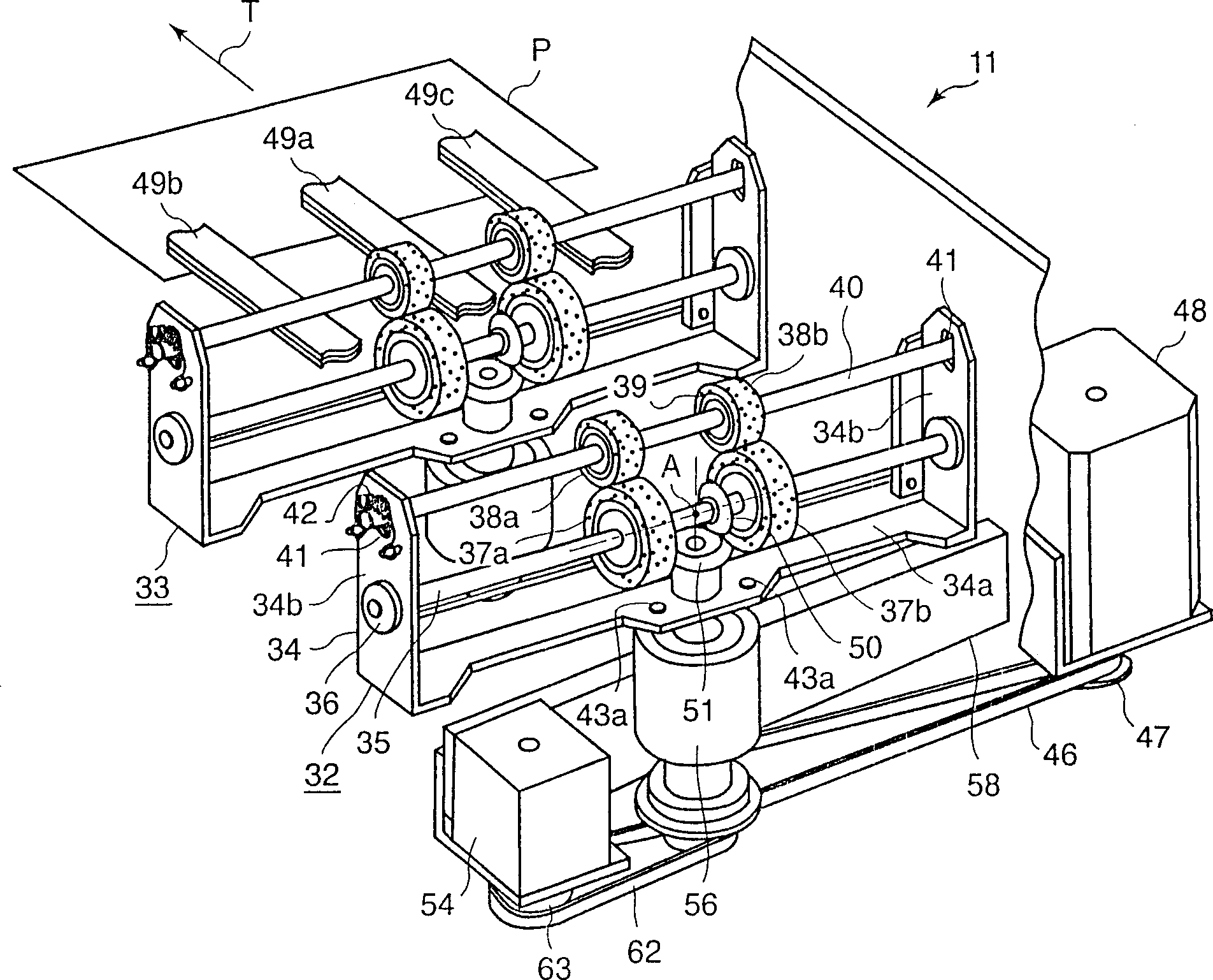
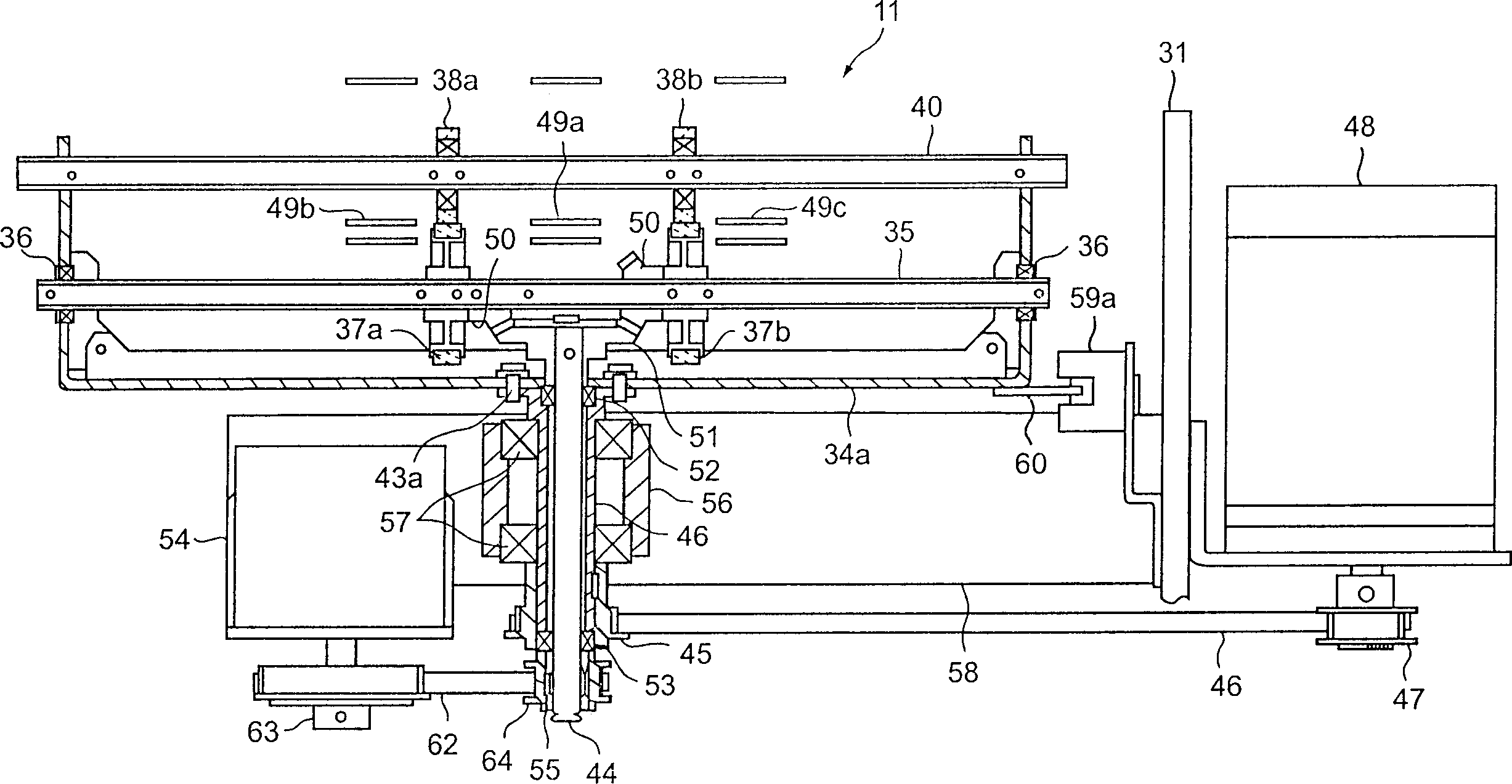
[0096] In this state, the controller 90 outputs a control signal to the posture correction controller 97 when the banknote P is judged to be fed to the first correction mechanism 32 according to a detection signal from a sensor (not shown) on the conveyor. Then the attitude correction controller 97 drives and controls the stepping motor 54 of the first correction mechanism 32 (step 1). As a result, the rubber rollers 37a, 37b, 38a, and 38b of the first correcting mechanism 32 rotate in the conveying direction at a peripheral speed equal to the convey...
no. 2 example
[0130] Whether the correction process should be executed or prohibited will be described below on the basis of the gap between the preceding banknote P and the current banknote P in the posture correcting device 11 .
[0131] The posture correction controller 97 judges the trailing edge of the preceding bill P and the leading edge of the current bill P based on the detection signal from the posture detecting bill P, and judges the gap (space) between the preceding bill P and the present bill P based on the judgment. .
[0132] In addition, instead of the signal from the posture detection sensor 70 , a detection signal from a transportation detection sensor (not shown) provided upstream of the posture correction controller 97 on the transportation path 7 may be used.
[0133] Refer below Figure 10 The flow chart shown in illustrates the attitude correction judgment operation.
[0134] Such as Figure 11 As shown, first, the case where there is a gap (space) g1 between the c...
no. 3 example
[0148] Next, in the attitude correcting device 11, it will be explained whether the displacement correction operation is performed on the basis of the gap (space) between the previous banknote P and the current banknote P and the displacement direction of the banknotes P1 and P2 or the correction operation is prohibited. .
[0149] In this case, the attitude correction controller 97 judges the trailing edge of the front banknote P1 and the leading edge of the rear banknote P2, and judges the gap (space) between the front banknote P1 and the current banknote P2 on the basis of the judgment. .
[0150] The attitude correction controller 97 further judges the displacement amount ΔS on the basis of the detection signal issued by the attitude detection sensor 70 .
[0151] then refer to Figure 13 The flowchart shown in illustrates the calibration operation.
[0152] First, the attitude correction controller 97 judges the rear end of the front banknote P1 and the front end of th...
PUM
 Abstract
Description
Claims
Application Information