
Loading tripod

A tripod, one-to-one correspondence technology, applied in the direction of machine/bracket, supporting machine, mechanical equipment, etc., can solve problems that cannot meet the requirements of use, and achieve the effect of improving load-bearing capacity and load-bearing stability

Active Publication Date: 2017-02-08
HUBEI SANJIANG SPACE XIANFENG ELECTRONICS&INFORMATION CO LTD
View PDF9 Cites 3 Cited by
  • Summary
  • Abstract
  • Description
  • Claims
  • Application Information

AI Technical Summary

Problems solved by technology

[0002] At present, tripods are widely used in photography, videography, engineering surveying and other fields. They mainly play a supporting role. Qi, A total station tripod anti-slip locking device, CN201320688652.X[P], 2013; Shen Zhaoqing, Zhu Ji, Meng Jie, A fall-proof measuring tripod, CN201420049368.2[P], 2014; Lu Qi, a An easy-to-carry camera tripod, CN201420294421.5[P], 2014), however, for slightly heavier equipment (more than 50kg), such as speed radars, these tripods can no longer meet their use requirements, and the radar has azimuth and pitch rotation tracking and positioning , which puts higher demands on the stability and fine-tuning of the tripod

Method used


Image

  • Loading tripod
  • Loading tripod
  • Loading tripod

Examples


Embodiment Construction

[0029] In order to make the object, technical solution and advantages of the present invention clearer, the present invention will be further described in detail below in conjunction with the accompanying drawings and embodiments. It should be understood that the specific embodiments described here are only used to explain the present invention, not to limit the present invention. In addition, the technical features involved in the various embodiments of the present invention described below can be combined with each other as long as they do not constitute a conflict with each other.

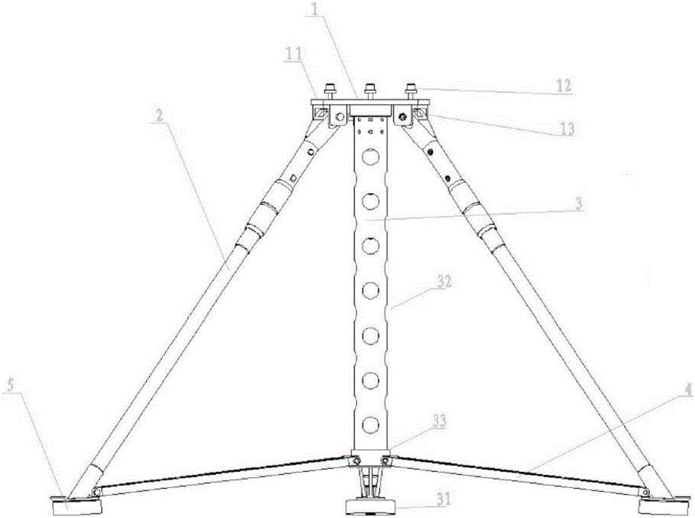
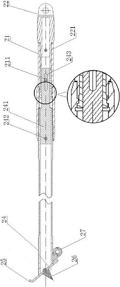
[0030] Combine below Figure 1-3 The present invention is described further.

[0031] Figure 1-3 It is the first embodiment of the present invention, including a load-bearing seat 1 , three fine-tuning legs 2 , a central load-bearing component 3 , and three struts 4 .

[0032] Bearing base 1 comprises base plate 11 and three rotating coils 12 that are arranged on the upper part of base plate...


PUM


Abstract

The invention discloses a loading tripod comprising a bearing base, three fine adjustment supports, a central bearing assembly and three supporting rods. The bearing base comprises a base plate, three rotation coils arranged on the upper portion of the base plate, and three hinges arranged on the lower portion of the base plate. The three hinges are distributed to form an equilateral triangle shape. The positions of the three rotation coils correspond to the positions of the three hinges in a one-to-one manner. Each rotation coil penetrates the base plate. The lower ends of the rotation coils are fixed to pivots of the corresponding hinges. The upper ends of the three fine adjustment supports are correspondingly pivoted to the three hinges in a one-to-one manner. The center bearing assembly comprises a base, a bearing rod and a slide sleeve. One end of the bearing rod is arranged on the base, and the other end of the bearing rod is fixed to the center of the base plate. The bearing rod is sleeved with the slide sleeve sliding between the base and the base plate. The three supporting rods correspond to the three fine adjustment supports in a one-to-one manner. One end of each supporting rod is connected to the lower end of the corresponding fine adjustment support in a pivoted manner, and the other end of each supporting rod is connected to the slide sleeve in a pivoted manner. Compared with the prior art, the loading tripod is suitable for tracking and positioning devices which are large in load capacity and have certain vibration impact environments.

Description

technical field [0001] The invention belongs to the technical field of load-bearing engineering, and more specifically relates to a load-bearing tripod. Background technique [0002] At present, tripods are widely used in photography, videography, engineering surveying and other fields. They mainly play a supporting role. Qi, A total station tripod anti-slip locking device, CN201320688652.X[P], 2013; Shen Zhaoqing, Zhu Ji, Meng Jie, A fall-proof measuring tripod, CN201420049368.2[P], 2014; Lu Qi, a An easy-to-carry camera tripod, CN201420294421.5[P], 2014), however, for slightly heavier equipment (more than 50kg), such as speed radars, these tripods can no longer meet their use requirements, and the radar has azimuth and pitch rotation tracking and positioning , which puts higher demands on the stability and level fine-tuning of the tripod. Contents of the invention [0003] The present invention aims to provide a tripod structure that can bear heavy weight (≥150kg), rea...

Claims


Application Information

Patent Timeline
Patent Type & Authority Applications(China)
IPC IPC(8): F16M11/32F16M11/04
CPCF16M11/04F16M11/32
Inventor 王院生
Owner HUBEI SANJIANG SPACE XIANFENG ELECTRONICS&INFORMATION CO LTD
Learn More