Two-stage speed variator device for converting electric tool

A technology for power tools and transmissions, applied in power tools, transmissions, gear transmissions, etc., can solve the problems of not having

Inactive Publication Date: 2003-04-23
ROBERT BOSCH GMBH
View PDF1 Cites 14 Cited by
  • Summary
  • Abstract
  • Description
  • Claims
  • Application Information

AI Technical Summary

Problems solved by technology

But this known gearshift slider does not have the device that can clearly identify being locked on this or that gear

Method used


Image

  • Two-stage speed variator device for converting electric tool
  • Two-stage speed variator device for converting electric tool
  • Two-stage speed variator device for converting electric tool

Examples


Embodiment Construction

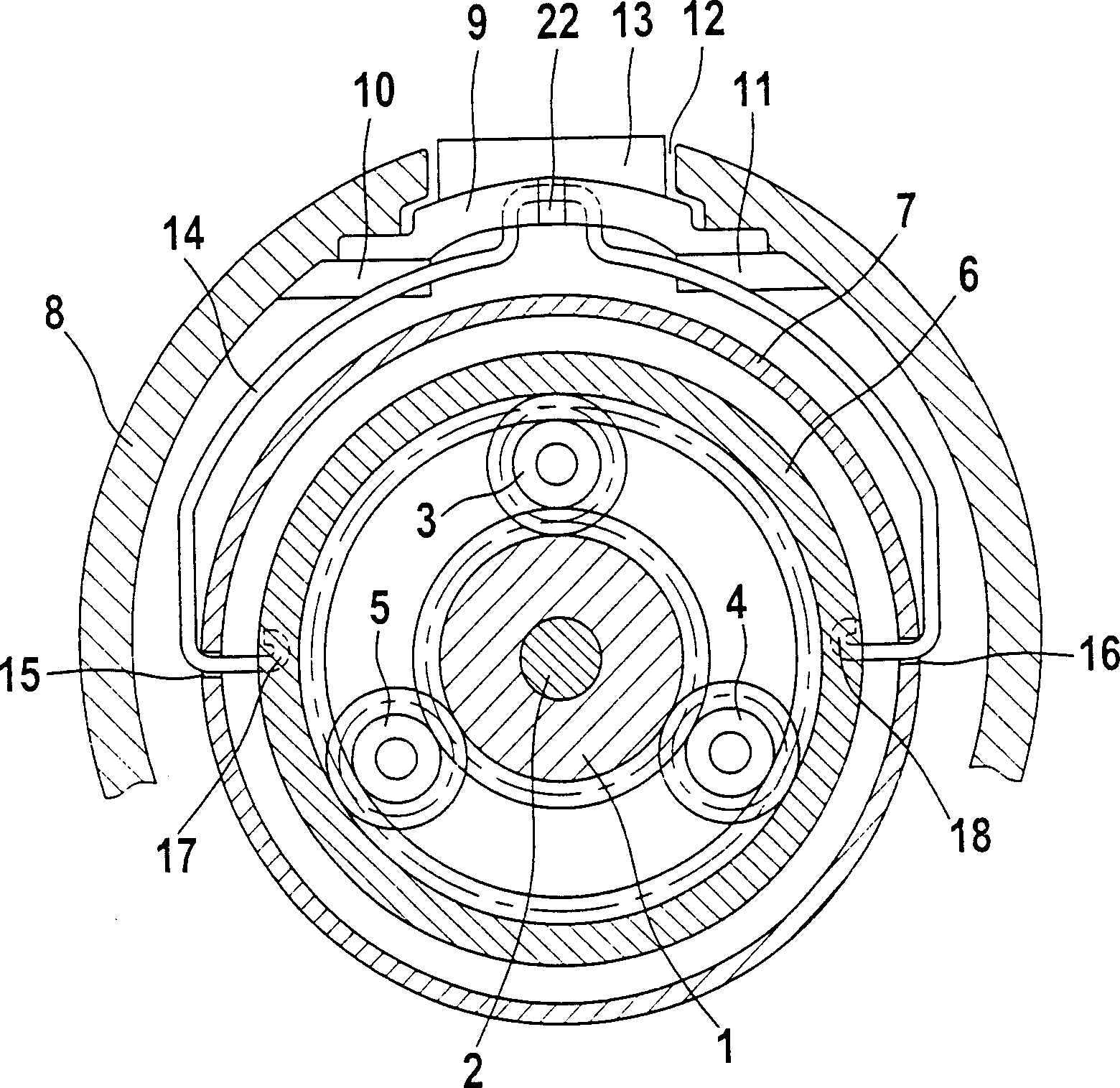
[0014] figure 1 A cross-sectional view of the planetary gear unit of a power tool such as a Bohrschrauber is shown in . This planetary gear unit comprises in a known manner - as can be seen from DE 39 04 085 A1 - a sun gear 1 which is non-rotatably connected to the drive shaft 2 of the electric motor, a plurality of planet gears meshing with the sun gear 1 3, 4 and 5, and an inner ring gear 6 surrounding the planetary gears and the sun gear, which meshes with the planetary gears 3, 4, 5. The entire transmission is enclosed in a transmission housing 7 . The ring gear 6 is supported movably in the axial direction of the drive shaft 2 . The axially displaceable ring gear 6 is used for shifting a planetary gear set designed here as two gears.

[0015] In the first position, the ring gear 6 meshes with a not-shown tooth portion on the transmission housing 7 so that it is fixed against rotation and the planet gears 3, 4 and 5 driven by the sun gear 1 are internally toothed. The ...


PUM


Abstract

In a device for switching a two-stepped type transmission device of an electrically-driven tool having a slider 9 which is supported by a tool casing 8 in a shiftable manner and movable and switchable to two switching positions with the switching slider coupled with a shiftable part of the transmission device, a leaf spring extending transversely to the shifting direction is fixed to supports 20 and 21 which are not moved together with the switching slider 9 at both ends thereof, the length of the leaf spring 19 is larger than the space between the supports 20 and 21, and the leaf spring 19 is coupled with the switching slider 9 in a friction-coupling manner.

Description

technical field [0001] The invention relates to a device for switching a two-stage transmission of an electric tool, which has a shift slide which is movably mounted on the tool housing and can be placed in two gear positions, the latter being connected to the The movable parts of the transmission form a functional connection. Background technique [0002] Such a shifting device for a two-stage transmission of an electric tool is known from DE 39 04 085 A1. A bracket is fastened to the shifting slide mounted displaceably in the tool housing, which engages in an axially displaceable shifting gear belonging to the transmission. The shifting bow has the properties of a spring element and thus has the function that when the shifting slide is actuated, the movable shifting gear shifts as soon as the next tooth-tooth position of the shifting gear and a fixed gear is reached. The blocking gear is engaged with its teeth on the fixed gear. However, this known shifting slide has no...

Claims


Application Information

Patent Timeline
Patent Type & Authority Applications(China)
IPC IPC(8): B25F5/00F16H3/54F16H59/04F16H63/04F16H63/38
CPCF16H59/041F16H63/38F16H3/54B25F5/001F16H63/04
Inventor 斯特凡·凯勒安德烈·比内尔
Owner ROBERT BOSCH GMBH
Why Eureka
Try Eureka